Each CD disc replays two-channel stereo signals for up to 74 minutes. The VCD video disc player needs to reproduce sound and images at the same time. The image signal data needs to be compressed, and the audio signal data is also compressed. Otherwise, the audio signal is difficult to store in the VCD disc.
This article refers to the address: http://
First, sound compression 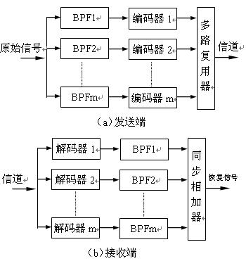
The inverse process of the transmitting end is implemented at the receiving end. Input sub-band encoded data stream, send each sub-band signal to corresponding digital decoding circuit (m total) for digital demodulation, pass through low-pass filters (m-channel), and re-demodulate The subband frequency domain is restored to the original distribution state of the original signal. Finally, each sub-band output signal is sent to a sync adder, which is added back to the original signal, and the recovered signal is very similar to the original signal.
(2) Sub-band coding application Sub-band coding technology has outstanding advantages. First, the amplitude values ​​of the frequency components of the sound spectrum are different. If different proportional coefficients are allocated to different sub-bands, the number of quantization levels of each sub-band and the corresponding reconstruction error can be controlled more reasonably, so that the code rate is further improved. Accurately match the source characteristics of each subband. Typically, near the low frequency pitch, a larger number of bits is used to represent the sampled value, while in the high frequency band, a smaller coded bit can be allocated. Secondly, by reasonably assigning the number of bits of different sub-bands, the total reconstruction error spectrum shape can be controlled. By combining with the acoustic mental model, the noise spectrum can be formed according to the subjective noise perception characteristics of the human ear. Thus, the use of the human ear hearing masking effect can save a large number of bits.
When subband coding is employed, the masking effect of the auditory is utilized for processing. It deletes some sub-band signals or greatly reduces the number of bits, which can significantly compress the total amount of transmitted data. For example, a sub-band where there is no signal frequency component, a sub-band of the signal frequency masked by the noise, a sub-band of the signal frequency component masked by the adjacent strong signal, etc., can be deleted. In addition, the amount of transmission information of the whole system is related to the frequency band range and dynamic range of the signal, and the dynamic range is determined by the number of quantization bits. If a reasonable number of bits is introduced to the signal, different sub-bands can be given as needed. Different bits can also compress the amount of information.
Second, MPEG-1 audio coding block diagram
1, the basis of MPEG-1 audio coding
The MPEG-1 audio compression coding standard uses a psychology algorithm. The perceptual model is used to delete the sound data that is insensitive to the hearing, so that the quality of the reconstructed sound is not significantly reduced. It adopts sub-band coding technology to obtain the auditory masking thresholds of different sub-bands according to the psychoacoustic model; the sampling values ​​of each sub-band are dynamically quantized. It applies different quantization steps for different frequency bands according to the variation rule of the small volume signal masking threshold caused by the large volume signal on different frequency bands, so as to retain the main signal, and discard the components that have little influence on the auditory effect, and undergo data compression. A reasonable bit stream can be obtained, and the original sound transmission rate of about 1.5 Mbit/s is reduced to 0.3 Mbit/s, that is, the compression rate can reach 1/5.
2, the coding process
Figure 2.3.2 is a block diagram of MPEG-1 audio compression coding based on MUSICAM (masked mode universal subband coding and multiplexing). The input signal is a sampled binary PCM digital audio signal, and the sampling frequency can be 44.1 kHz, 48 kHz or 32 kHz. The code value of the audio digital signal is proportional to the amplitude and frequency of the original sampled signal. 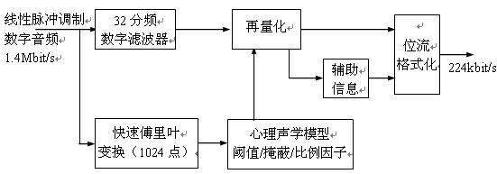
The digital audio signal first enters the digital filter bank, which is divided into 32 sub-bands of equal bandwidth, and 32 sub-band data signals can be output by the digital filter. This processing method is similar to the image-encoded signal performing DCT transform, but is not divided into 64 cosine frequency information like the image signal. Here, only 32 sub-bands are divided, that is, the audio data stream is changed to a combination of 32 frequencies. The resolution of the sound is lower than the image, and this processing method is feasible. Then, the audio data of the 32 sub-bands is re-quantized to recompress the amount of data. The quantization step size for each sub-band is different, and the quantization step size is determined according to the hearing threshold and the masking effect of the human ear. The quantized compressed data retains the main part of the audio information, and discards the audio information that has less impact on the auditory effect.
Entering the input signal of the coding system, the shunt part signal is sent to the parallel 1024-point fast Fourier transformer (FFT) for transforming, which detects the intensity of the distribution of the sampling point of each input signal in the frequency domain of the main spectral component, the transformed signal Send to the psychoacoustic model control unit. According to the auditory psychoacoustic measurement statistical results, a psychoacoustic control comparison table can be summarized, and the control unit is made according to the table, and the unit circuit can collectively reflect the threshold characteristics and the masking characteristics of the human ear.
The quantized 32 sub-band data has been compressed, and auxiliary information such as a scale factor and bit allocation information is added to the 1-bit stream formatting unit, and the code becomes a two-level audio coded signal. It contains 32 sub-band audio numbers, and the bit allocation data corresponding to these numbers and the strength ratio factors of different frequency band data. When the data is to be decoded in the future, the sound signal can be recovered according to the data of each sub-band, and the code bit allocation and the ratio of the strength and the weakness at the time of compression can be restored by referring to the program at the time of compression.
It can be seen that the compression coding of the sound is processed, such as transformation, quantization, and code bit compression. It uses many mathematical models and statistical data of psychoacoustic measurements to process the signals of 32 sub-bands and various levels. Each has a different sampling rate. The actual psychoacoustic model and the timely processing control process are very complicated. The details of these algorithms have been solidified in the decoder chip in hardware, and these contents can no longer be changed.
3. Synchronization of sound and image
There are many different methods for compressing image and sound signals. The amount of image data is much larger than the amount of sound data. The data rate transmitted by the two is very different. Only one audio data packet is transmitted for every 14 to 15 video data packets transmitted, and the content of the sound and image to be played must be well synchronized, otherwise the uniform effect of audiovisual will not be guaranteed.
In order to synchronize the sound image, MPEG-1 uses an independent system clock (referred to as STC) as the reference for encoding, and divides the image and sound data into many playback units. For example, dividing an image into frames, the sound is divided into paragraphs. In the data encoding, a display time stamp (PTS) is added in front of each playback unit, or a decoding time stamp (DTS) is added. When these time stamps appear, it means that the previous playback unit has ended and a new image and sound playback unit starts immediately. When playing the same image unit and sound unit corresponding to each other, mutual synchronization can be achieved.
In order to make the entire system have a common clock reference when the clock is being encoded and reproduced, the concept of the system reference clock SCR is introduced. The system reference clock is a real-time clock whose value represents the actual playback time of the sound map. It is used as a reference reference to ensure that the transmission time of the sound image signal remains the same. The real-time clock SCR must be consistent with the real time in life, and its accuracy is required to be high. Otherwise, sound and images may be broadcasted or slowed down. In order to make the SCR time reference stable and accurate, MPEG-1 uses the system clock frequency SCF as the reference basis for timing information. The frequency of the SCF system clock is 90KHz, and the frequency error is 90KHz±4.5KHz. The sound image signal is based on SCF, and other timing signals SCR, PTS, and DTS are also based on it.
Third, other MPEG standard audio encoder
1, MPEG-2 audio coding block diagram
MPEG-1 handles two-channel stereo signals, while MPEG-2 handles 5-channel (or 7-channel) surround sound signals, making it more realistic.
Figure 2.3.3 is a block diagram of the MPEG-2 audio coding. It inputs independent 5-channel audio signals, with front left and right main channels (L, R), front center channel (C), and rear left and right surround channels (LS, RS). . After the analog-digital conversion of each sound source, the sub-band filter is first input, and each channel is divided into 32 sub-bands, and the bandwidth of each sub-band is 750 Hz. In order to be compatible with MPEG-1, normal two-channel stereo and surround analog stereo, the original MPEG-1 encoded stereo channel can be expanded to multiple channels, and should include all five channels of information. Circuit. The circuit generates compatible legacy stereo signals LO, RO, and “weighted†left, center, right, left surround, and right surround sound signals (5 channels total). Reason for "emphasis" processing of 5 surround sound signals: When calculating compatible stereo signals (LO, RO), in order to prevent overload, all signals have been attenuated before encoding, and can be distorted by weighting; The matrix transition also includes the processing of attenuation factors and similar phase shifts.
The original signal of the encoder is 5 channels, and the input channels are 5. After the matrix conversion process, 7 kinds of sound signals are generated. A channel selection circuit should be provided, which can perform reasonable selection processing on 7 signals as needed. The process is determined by the process of solving the matrix and the allocation information of the transmission channel; reasonable channel selection is beneficial to reduce the noise interference caused by artificial noise processing. In addition, a multi-channel prediction calculation circuit is provided to reduce the redundancy between channels. When multi-channel prediction is performed, the compatible signals LO, RO in the transmission channel can be calculated from MPEG-1 data. Physiological acoustic basis
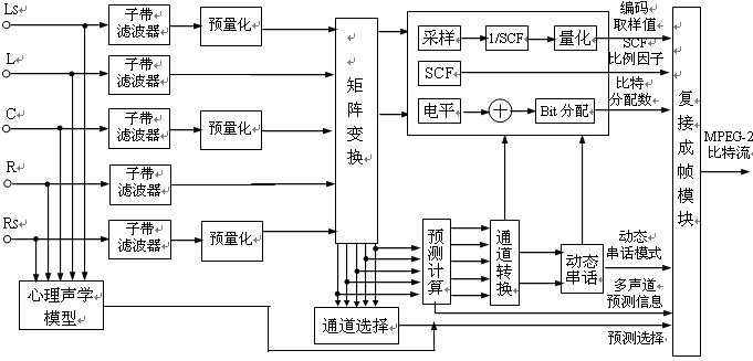
Basically, the latter stage sets up a dynamic crosstalk circuit that can improve the sound quality given a bit or reduce the bit rate if sound quality is required. But setting this circuit increases the complexity of the MPEG-2 decoder.
The encoder generates a variety of information, mainly including coded sample values, scale factors, bit allocation data, dynamic crosstalk mode, multi-channel prediction information, channel prediction selection signals, etc., and the information is transmitted to the multiplexed framing module circuit. Finally, the compression encoded signal is output in the form of an MPEG-2 bit stream.
The MPEG-2 decoder is basically the inverse process of the encoder, and its circuit structure is simpler and the amount of calculation is smaller. The decoding conversion matrix of the decoder can output 5 signals, and then processed by 32-divided sub-band filter, which can output LS, L, C, R, RS signals; in addition, after quantization, SCF and sub-band filter processing, The front stereo LO and RO can be obtained, and a total of 7 audio signals can be output.
2, MPEG-4 audio decoding
MPEG-4 audio coding, like MPEG-4 video coding, has many features and functions such as scalability, limited time audio streaming, audio change/time scale variation, editability, and latency. It has excellent interactive performance and high compression ratio. It not only uses grading methods to edit language and music, but also solves synthetic language and music problems. It will become a major format in the multimedia world and will become a "all-round" system.
With MPEG-4 audio encoding, a variety of audio content can be stored and transmitted. It has high quality audio signals (mono, stereo and multi-channel). It uses low bit rate encoding, and the sound playback quality is very high. It can transmit wideband speech signals (such as 7KHz wide voice) or narrow bandwidth speech signals (such as long distance calls). Various speech signals that can be understood can be transmitted and produced. Languages ​​can be synthesized, such as phoneme or other token-based text conversions; audio can also be synthesized, for example, to support music description languages.
Fourth, Dolby AC-3 technology
1. What is Dolby AC-3?
Based on Dolby Pro Logic Surround Sound Technology, in 1990 Dolby teamed up with Japan's Pioneer to introduce a new all-digital Dolby Digital surround sound system using advanced digital compression technology. It allows more information on the multichannel signal to be compressed into the two channels, and this system is called AC-3. AC is an abbreviation for the English "Audio Sensing Encoding System". The AC-3 technology was first applied to the cinema and later to the ordinary family.
The Dolby AC-3 system sets up completely independent 6 channels, the full-band left, center, right, left surround and right surround channels, plus a subwoofer channel. Due to the structure of such a channel, the AC-3 system is also referred to as 5.1 channel.
2, the basic principle of Dolby AC-3
(1) Applying the auditory masking effect to develop an adaptive coding system
The theoretical basis of AC-3 technology is also the use of auditory thresholds and masking effects in psychoacoustics, but the technical aspects are different from the MPEG standard.
When data processing is performed on an audio signal, data compression is performed, and data information that is not useful or has little use is ignored. To this end, the auditory threshold and the masking rule can be applied to omit those redundant data information. In addition to the above acoustic principles, Dolby has developed its digital "adaptive coding" system using its Dolby noise reduction technology. This is an adaptive coding system with very selective and noise-suppressing capabilities. Based on the basic principles of acoustic psychology, Dolby maintains a quiet state when no music signal is input; when inputting a music signal, it analyzes and decomposes complex audio signals, masks noise with strong signals, and removes hearing boundaries. Or because of the close frequency and low volume signal, this processing method can greatly reduce the data information that needs to be processed. The human ear's hearing range is 20Hz-20KHz. In such a wide frequency range, the human ear has great differences in auditory sensitivity to different frequencies. According to this feature, Dolby AC-3 divides the audio channel of each channel into a number of narrow bands of different sizes. Each sub-band is close to the width of the critical band of the human ear, retaining effective audio and tightly different noise frequencies. The encoding is performed with each channel signal, that is, the encoding noise can only exist in the frequency band of the encoded audio signal. This allows the encoding noise to be filtered out more steeply, and the encoded noise of the unwanted and unaudited signals in the band is reduced or removed, and the useful audio signal is preserved. The AC-3 system accurately uses the masking effect and the "common bit group" design method to greatly improve data compression efficiency and have a high level of sound quality. The system's bit rate is based on the needs of individual spectrum, or the dynamics of the source, and is distributed to each narrow band. It is designed with a built-in auditory masking program that allows the encoder to change its frequency sensitivity and time resolution to ensure There are enough bits to be used to mask out the noise and to record the music signal well.
In order to efficiently utilize a limited information transmission medium (optical disk, film, etc.), it compresses the audio signal and, like other compression systems, uses the auditory characteristics of the human ear to combine the coefficients of certain channels according to the specific circumstances at the time ( These channel coefficients reflect the amount of energy in that band) in order to increase the compression ratio. Not all channels can do this kind of merging. The encoder can be automatically determined and adjusted according to the information characteristics of each channel. Only similar channels can be mixed together. If the compression ratio is not high, it is not necessary to merge. In general, the higher the starting frequency of the combination, the better the sound quality, but the higher the data transmission rate. When the sampling frequency is 48KHz, the combined starting frequency should be 3.42MHz; if the sampling frequency is 44.1KHz, the starting frequency should be 3.14MHz. If the hardware and software are properly matched, the sound quality of the AC-3 can reach or approach the level of the CD record.
(2) Simple block diagram of Dolby AC-3 decoder
The AC-3 decoder input signal is a set of spectral signals obtained by time-frequency transform of the time domain signal PCM data. The spectral data stream is divided into two parts: an exponential part and a mantissa part. The exponential part is coded by a differential method. The encoded index represents the spectrum of the entire signal and can be used as a parameter of the spectrum envelope. The mantissa portion is quantized according to the result of the bit allocation. Thus, the quantized mantissa and the spectral envelope form the primary information of the AC-3 codestream, along with other auxiliary signals (e.g., bit allocation, etc.) to form the AC-3 bitstream.
Figure 2.3.4 is a block diagram of the decoding of the AC-3 system, which is the inverse of the AC-3 encoding. The AC-3 bit stream first enters the buffer stage, and then performs error correction using the frame as a processing unit. After error correction processing, the fixed data (index data, matching coefficient, mode symbol, etc.) in the bit stream is decoded to make the data bits. The stream is restored to the original bit allocation.
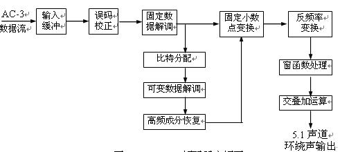
Then, the data signal is divided into two ways. One of them, after restoring the bit stream to the original bit allocation, determining the size of the quantisation of the mantissa portion, and then decoding the variable data in the bit stream; and then restoring the high frequency components to prepare for the inverse frequency transform. Finally, the exponential part data and the mantissa part data are merged, converted into fixed decimal point data, and then frequency-converted to obtain time-axis data. The data signal that has been restored to the time domain needs to be window processed, and the overlap addition is performed to obtain the output signal of the 5.1 surround channel.
3. Features of Dolby AC-3
(1) Configure 5.1 channel to decode the input audio signal, you can output 5.1 channel signal, including 3 front channels (L, C, R), and 2 rear surround channels (LS, RS), they are independent of each other, and the frequency response width is in the full audio frequency range, that is, 20Hz-20KHz (±0.5dB) and 3Hz-20.3KHz (-3dB), and the frequency response of each channel is very wide. Currently, the Dolby Pro Logic Surround Sound System, which is widely used in audio systems, cannot be compared to the Dolby AC-3 bandwidth. Also, the Dolby Pro Logic Surround System is a 4-channel system with front left, center, right and rear surround sound, and its surround sound is mono surround sound, two rear surround channels. Replay the common sound signal, the two channels are connected in parallel or even in series; the frequency response of the surround sound is limited to 100Hz-7KHz; in addition, it does not have a separate subwoofer channel, it is by the front left, The right channel separates the 20Hz-120Hz subwoofer to reproduce the subwoofer with a powerful effect. The AC-3 system is equipped with an independent ultra-low channel with a frequency response of 20Hz-120HZ (±0.5dB) and 3Hz-121Hz (-3dB). The volume of the ultra-low speaker is 10dB larger than other channels. Shocking low effect.
(2) Each channel is fully digital and independent of each other
Each channel of the AC-3 carries different signals independently of each other and is a fully digital audio signal. The sampling frequency is 32, 44.1 or 48KHz, the data transmission capacity is 32kb/s-640kb/s per channel, the typical value is 384kb/s in 5.1 channel mode, and the typical value is 192kb/s in dual channel mode. After digital processing, the frequency of the five main channels is compressed in the range of 20Hz-20KHz.
(3) The 5.1 channel compressed output can be used as a "guidance signal" for each program mode (mono, stereo, surround sound, etc.) in the "bit stream" of AC-3, enabling AC-3 automatic The location of the program is indicated to the user. It compresses 5.1-channel signals into two channels for recording regular VHS tapes or as an input source for Dolby Surround to be compatible with it, even compressing 5.1-channel signals into mono output . In summary, the AC-3 can output 5.1-channel Dolby Surround, mixed 4-channel Dolby Surround, 2-channel stereo and mono. The 5.1 channel data is compressed to occupy a narrow frequency band. For example, the AC-3 data code can be encoded in the frequency band occupied by the right channel of the FM modulation of the LD player, and the AC-3 RF signal is output. The center frequency is taken at 2.88MHz, and the AC-3 coded signal with a frequency of 2.88MHz can be taken out by the LD's original analog output right channel. Thus, the entire contents of the 5.1 channel can be accommodated in the original analog channel.
(4) Sound time calibration makes the sound ideal. The Dolby AC-3 passes all the channels through the “time calibration†technology, so that each speaker sounds the same distance as the listener to produce better sound. The surround sound effect is not only the front, rear, left, and right sound sources are positioned clearly, but the upper and lower sound fields are also clearly distinguishable.
Four Burner Gas Cooker,Stainless Steel Gas Stove,Ce Table Outside Gas Cooker,4 Burner Glasstop Gas Cooker
xunda science&technology group co.ltd , http://www.gasstove.be