In recent years, the rapid development of computer technology, multimedia technology and data communication technology has led to the increasing use of digital video (such as video surveillance, video conferencing and mobile TV). Subsequently, the study of various compression algorithms made the storage and transmission of digital video extremely convenient, and various video recording systems have appeared one after another. The embedded video recording system designed in this paper can convert the analog video data captured by the camera into digital video data, which is compressed and stored in a large-capacity memory, and can reproduce the whole process of the car through a dedicated playback device. The video recording system can be used to record video information and emergency markers such as various instruments in the car and front and exterior views, and it can continuously and continuously record all the information in the process of the car in digital video. The system can be combined with the black box of the car to facilitate the management department to effectively manage the vehicle according to the recorded data, and to provide an accurate basis for the analysis after the accident and to determine the real cause of the accident. At the same time, it is possible to analyze and improve bad driving habits by recording whether to check whether the emergency data is urgently accelerated or not, and to prevent accidents.
This article refers to the address: http://
A common video compression method is the MPEG series rent H.26X series. Taking into account the maturity, cost and main use of compression technology, this recording system uses MPEG-1 digital image compression recording technology to achieve real-time circular recording of continuous images of 1 channel of video signals for up to 4 hours. In addition, the video recording system has the characteristics of low cost, small size, and low power consumption.
1 System working principle
The focus of video recording system design is to reduce costs and reduce volume while reducing system power consumption and improving overall system performance. It can perform continuous real-time dynamic cycle recording of up to 4 hours on one video signal on the car. The system is mainly composed of video decoding and compression encoder, ARM processor and electronic disk. The video decoder and the compression encoder together form a compression unit, the ARM processor is a control unit of the system, and the electronic disk is a storage unit of the system. The structure of its video recording system is shown in Figure 1. When the system works, the video signal captured by the camera is first decoded and A/D converted by the video decoder SAA7113 H to output an 8-bit 4:2:2 format YCbCr digital video signal, and the digitized video signal is sent to the SZ1510 compression. After the encoding chip is compressed, an MPEG-1 data stream can be generated, and then the compressed data is stored in the storage carrier-electronic disk by the ARM processor through the IDE interface, thereby realizing continuous real-time cyclic recording of the 1 channel video signal.

After the system is powered on and started, the ARM processor first configures the SZ1510 internal register through the HOST interface of the SZ1510 chip, and initializes the video decoder SAA7113H through the I2C bus. After setting the MPEG-1 compression format and data rate, the system starts to work normally, and the input analog video signal is decoded and A/D converted by the video decoder, and then the generated CCIR-601 digital video stream is transmitted and compressed. The chip SZ1510 is processed, and then the digital video data is converted into a video file conforming to the MPEG-1 format by the SZ1510. Finally, the MPEG-1 data stream is written into the electronic hard disk through the IDE interface under the control of the ARM processor for storage. When the system works, ARM will continuously monitor the relevant signals and add corresponding flags to the image until the shutdown signal is received, and the system automatically ends the compression work.
2 hardware circuit design
2.1 Video decoding and compression coding circuit design
Since the MPEG-1 compression algorithm requires a large amount of computation, it is difficult to complete in real time using software, so the system uses a dedicated video compression chip to achieve real-time efficient compression of the video signal. At present, commonly used MPEG-1 compression chips are VW2010, W99200F, WIS 7007SB and the like. This design uses SAA7113H for decoding, and uses Zapex's SZ1510MPEG-1 A/V encoding chip for image compression. The main function of the SAA7113 is to decode the input analog video signal into a standard 8-bit "VPO" digital signal. It is equivalent to an "A/D" device and is a programmable video processing chip that can be implemented via the I2C bus. Programmable control with 4 video inputs, anti-aliasing filtering, auto-clamp and gain control, multi-format decoding, and brightness, contrast, and saturation control. It samples and decodes incoming PAL video signals. The generated CCIR-601 digital video stream (yellow space YCbCr, sampled as 4:2:2) can be sent to the digital video input interface of the video compression chip SZ1510. Its input clock is provided by an active crystal oscillator of 24.576 MlHz. And the line sync signal HS and the field sync signal VS provided for the SZ1510 can be output from the RTS1 and RTS0 pins respectively, wherein the line sync signal HS can be input as the line effective pixel identification signal to the VIHACT pin of the SZ1510; and from the LLC The pin outputs a pixel clock of 27 MHz, which is used as the sampling clock of the digital video stream inside the SZ1510 and the master clock of the chip. The system initialization can be realized by the I2C bus of the ARM chip.
The compression coding chip SZ1510 in the system is a high-performance MJPEG and MPEG-1 encoding chip produced by ZAPEX, which can achieve up to 25 f/s compression for video signals and supports multiple working modes and bit rate modes. Flexible combination of modes, with video markers and time stamps superimposed on the video. The chip is mainly composed of video encoding core, TMS320C54X high-performance DSP core, interface circuit (video interface, memory interface, host and serial port interface), DMA controller and clock generation circuit. Its internal compression core has been optimized for efficient, real-time MPEG-1 digital image compression, and features many features, low power consumption, and wide temperature range.
The SZ1510 in the system is a slave device and is controlled by the host ARM. Its HOST interface is the interface for control and data exchange. The SZ1510 can choose from a variety of bus types. It has multiplexed and non-multiplexed Intel and Motorola bus types (in the multiplex mode, HAD[7:0] can be used as a data line or as an address line; non-multiplexed mode When HAD[7:0] can only be used as a data line), it can be divided into 8 bits and 16 bits without multiplexing the bus, and can be selected and configured by the HCONFIG[l:0] pin and the Syscofig[3] register. This system sets HCONFIG0 low, HCONFIG1 is set high, and Sysconfig[3] writes 1, so it can work in Intel 8051 type non-multiplexed 16-bit data bus mode.
Because the SZ1510 has multiple working modes, this design allows the SZ1510 to work in LVE (Live Video Encoding) real-time video encoding mode according to system requirements. In this mode, the SZ1510 can obtain real-time digital video data from the video decoder, then compress it according to MPEG1/M-JPEG and transmit it to the host. The specific working process is: SZ1510 performs video preprocessing, automatic clipping, scene change detection, motion estimation, motion compensation, discrete cosine transform/anti-discrete cosine transform and variable length coding on the CCIR-601 digital video stream input to its internal After processing, the generated MPEG-1 video elementary stream is stored in the SDRAM, and then outputted through a FIFO buffer having an output port size of 256 bytes. In normal operation, a FRDY (FIFO Read) interrupt is generated every time the FIFO is full to inform the host to read the data in the FIFO, and the host reads the data from the Data_out register. After that, when the SZ1510 issues an EOD (end of data) interrupt, the data transfer ends.
In the video compression mode, the SZ1510 has three output bit rates to choose from: constant bit rate, maximum bit rate, and variable bit rate. The constant bit rate requires padding redundancy, the maximum bit rate does not need to be padded for redundancy, and the compression quality of the variable bit rate is variable compared to the constant bit rate. The bit rate can be selected by setting the 1 and 2 bits of the Ven_cntl register. When it is 0, the constant bit rate is selected; when 1, the maximum bit rate is selected; when 3, the variable is selected. Bit rate.
2.2 Control and storage circuit design
Taking into account the volume, reliability and control of the control part, the CPU in this system uses Philips' ARM7TD-MI-S core microcontroller LPC2210. This is a 16/32-bit ARM7TDMI-S CPU that supports real-time emulation and tracing. For applications with tightly controlled code size, the 16-bit Thumb mode can be used, which reduces code size by more than 30%, while performance loss is minimal. The LPC2210 is available in a 144-pin package with very low power consumption. In addition, the chip has multiple 32-bit timers, eight 10-bit ADCs, PWM outputs, and up to nine external interrupts. The LPC2210 provides up to 76 GPIOs by configuring the bus.
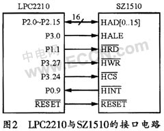
The LPC2210 can be connected to the HOST interface of the SZ1510, and the SZ1510 can be controlled and set via the HOST interface. In normal operation, the LPC2210 sends the MPEG-1 format video stream output from the HOST interface to the electronic disk for storage in the form of a file. The interface circuit of LPC2210 and SZ1510 is shown as in Fig. 2. Among them, HAD[0...15] is connected to ARM's P2.0~P2.15A as 16 data lines; P3.0 is connected to HALE pin to realize SZ1510 internal IOAR (I/O Address Registerl) and IODR (I/O) DataRegister) register selection; P1.1 and P3.27 read and write strobe pins HRD and HWR respectively; connect P3.24 to HCS to pass SZ1510; connect P0.9 to HINT to send SZ1510 interrupt Request signal.
Starting from the weight and reliability, this recording unit is finally realized by an electronic disk. The main body of the electronic disk is a Flash chip, which is resistant to impact, high temperature, small in size and long in life, and is suitable for working in an automobile environment. Although the price of the electronic disk is expensive, considering that the system only collects one channel of video signal, the amount of recorded data is not very large (the calculated capacity of the recording unit is 3G after calculation), and the recording length can reach 4.5 hours, so The use of an electronic disk is fully capable of fulfilling the mission requirements.
The connection circuit between the GPIO pin of the LPC2210 and the IDE interface is shown in Figure 3. In the figure, P2.16~P2.31 are data lines, P1.16~P1.20 are address and strobe signals, P0.17 and P0.20 are device reset and status request signals, with P0.21 and P0 .19 can achieve read and write control.

3 system software design
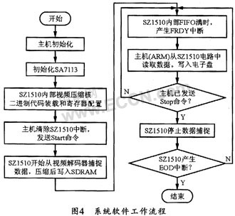
All software programs of this system should be burned into ARM through the JTAG port in advance, so that these programs can be automatically run after the system is powered on to control the system. The system software work flow chart is shown in Figure 4.
3.1 SZ1510 register configuration
The SZ1510 has 128 registers, each of which has an index number. The external host uses the HOST interface (HALE pin) to set the two internal registers of the SZ1510, IOAR (I/O address register) and IODR (I/O data register). ) to achieve control and configuration of the SZ1510. When accessing, first send a low level to the HALE pin by the host's A0 pin to select the IOAR register, then write the register index number to be accessed to the IOAR; then send a high level to the HALE tube by the host's A0 pin. To select the IODR register, then write the data to be written to the IODR, so that the SZ1510 will automatically send the configured data to the register at the specified address.
When initializing the Z1510, the host first writes any value to the 0x0B register. Then, after the host waits for at least 1 microsecond, write 0x40 to the Int_enable interrupt enable register to enable the RDY (Ready) interrupt. Then, the host waits. The SZ1510's Ready (Int_source[6]) interrupt; after that, when the host waits for the RDY interrupt, it clears the RDY interrupt and begins loading the binary code into the SZ1510's internal DSP.
3.2 Binary code loading of SZ1510
Since the contents of the internal registers are unknown after reset, the host must load the program code to initialize the programmable RAM of the video encoding core. The program space inside the SZ1510 is divided into blocks, and the size of each block is 256 bytes. The binary code for the video encoding core has a load space of 0x000 to 0x004 and 0x00c, and a total of 1.5k bytes of code. For specific loading, the host first writes 0x01 to the 0x2E register to indicate that the external SDRAM is 1M×16bits; then the host writes 0x03 to the 0x0C register to enable the FIFOReady and End of Data interrupts; then the host writes 0x1 to the 0x11 register. Set the working mode to the internal memory write mode; then the host writes 0x20 to 0x10 to set the FIFO size of the SZ1510 output data to 256 bytes; finally, binary code loading is performed for each program space. The specific process is as follows:
(1) The host writes the 0x3F register and selects the download program space;
(2) The host writes 0x04 to the 0x08 register and sends a start command.
(3) The host waits for the Ready interrupt;
(4) The host clears the Ready interrupt by reading the 0x0e register;
(5) The host writes 256 bytes to the Data_in register 0x01;
(6) The host waits for an EOD (End 0f Data) interrupt.
(7) The host clears the EOD interrupt by reading the 0x0e register;
(8) The host checks whether the code of the program space is loaded, and if not, continues to load.
4 Conclusion
The system can record the video signal displayed by the camera outside the vehicle and the instruments in the vehicle for a long time in real time, and the recorded compressed data stream conforms to the MPEG-1 image compression standard. The compressed video flow rate used in this design is 1.5 Mbps. For a 3GB electronic disk, the system can continuously record more than 4.5 hours of car video data. It can be seen that the system is small in size and low in power consumption, and is convenient for real-time long-term compressed data recording of video data in a mobile environment.
For 2835 SMD LED. They can be all kinds of wavelength's SMD LED , include the visible Light and the unvisible light.
Dome Lens SMD LED is a great substitute for DIP LED(Through-hole LED)

In this catalog, we mainly introduce the 2835 Dome Lens SMD LED, 3528 domed LED and 5050 dome LED of visible light. 2835 SMD LED, size is 2.8*3.5mm. For this SMD LED, we can supply all kinds of visible wavelength and color on it. such as: purple LED, blue LED, cyan LED, lime LED, green LED, Yellow LED , Amber LED , Orange LED , red LED, deep red LED, red grow light LED , white LED, warm white LED, pink LED and so on.
3528 SMD LED , size is 2.8*3.5mm. For this SMD LED, we can supply all kinds of visible wavelength and color on it. such as: purple LED, blue LED, cyan LED, lime LED, green LED, yellow LED, amber LED, orange LED, red LED, deep red LED, red grow light LED , white LED, warm white LED, pink LED and so on.
5050 SMD LED, size is 5.0*5.0mm. For this SMD LED, we can supply all kinds of visible wavelength and color on it. such as: purple LED, blue LED, cyan LED, lime LED, green LED, yellow LED, amber LED, orange LED, red LED, deep red LED, red grow light LED , white LED, warm white LED, pink LED and so on.
Dome Lens SMD LED
2835 Dome Lens SMD LED, 3528 Domed LEDs, 5050 Domed LEDs, High Power LED Lens
Shenzhen Best LED Opto-electronic Co.,Ltd , http://www.bestsmd.com