Weak electrical signal. The signal is coupled to the base of VT1 via capacitor C1 for amplification. The amplified signal is output by its collector, coupled to VT2 via C2 for second stage amplification, and finally the signal is output by the VT3 emitter and sent through jack XS. Play the sound to the earphones.
In the circuit, C4 is a bypass capacitor, its main function is to bypass the various harmonic components forming noise in the output signal to improve the sound quality of the earphone. C3 is a filter capacitor, which is mainly used to reduce the AC internal resistance of the battery G (actually providing a good path for the audio current of the whole machine), which can effectively prevent the self-oscillation generated by the circuit when the battery is quickly discarded, and the sound of the earphone More clear and loud.
Second, the component selection VT1, VT2 select 9014 or 3DG8 type silicon NPN low power, low noise triode, requires current amplification factor β ≥ 100; VT3 should choose 3AX31 type 锗 PNP low power triode, requires the penetration current Iceo as small as possible Some, β≥30 can be.
B selects CM-18W type (φ10mm×6.5mm) high sensitivity electret microphone, its sensitivity is divided into five gears, which are represented by color points: red is -66dB, small yellow is -62dB, rhubarb is -58dB, The blue color is -54dB and the white color is >-52dB. White point products should be used in this production to obtain higher sensitivity. B can also be directly replaced with a blue point, high sensitivity CRZ2-113F electret microphone. 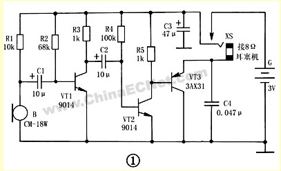
XS selects the two-core jack commonly used in CKX2-3.5 type (φ3.5mm caliber) earphones, which can be used after being purchased. For the modification method, as shown in Fig. 2, the inner reed piece clamped by the tweezers is slightly bent downward, and the inner and outer reeds are changed from the original normally closed state to the normally open state. After the plug is inserted, the inner and outer reeds can be reliably connected, and the plug can be reliably separated after being pulled out, so that it can also be used as a power switch. The headset uses an 8Ω low-impedance earphone with a CSX2-3.5 (φ3.5mm) two-pin plug.
R1 to R5 use RTX-1/8W type carbon film resistors. C11 to C3 use CD11-10V type electrolytic capacitors, and C4 uses CT1 type ceramic dielectric capacitors. G is made up of two series of No. 5 dry batteries in series with a voltage of 3V. 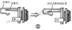
Third, production and use <br> Figure 3 shows the printed circuit board wiring diagram of the hearing aid. The actual size of the printed circuit board is approximately 60 mm x 50 mm. The printed board does not have to be corroded, as long as the unused copper foil is cut open with a knife. The battery clip can be made of 4 pieces of rectangular phosphor bronze pieces with a size of about 20mm×8mm, bent into an “L†shape, and a small hole is placed on each of the legs, and is directly riveted to the circuit board with copper rivets. 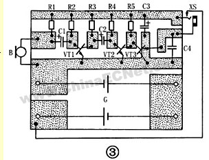
The soldered circuit board is housed in a fine plastic or plexiglass box measuring approximately 64 mm 54 x mm x 18 mm. The sound box and the mounting hole are opened for the microphone B and the jack XS in advance on the panel panel and the upper side. The shape of the assembled deaf hearing aid is shown in Figure 4. 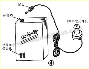
The debugging of the machine is very simple: first, by adjusting the resistance of the resistor R2, the VT1 collector current (the DC mA meter is connected in series in the R3 loop) is about 1.5 mA; then, by adjusting the resistance of the R4, the total static of the hearing aid is made. The current (the DC mA meter is connected in series with the power supply circuit of the battery G) can be around 10 mA. Because the B-parameters of the electret microphones used by each person are different, sometimes the resistance value of R1 needs to be adjusted appropriately, and the sound should be adjusted to the loudest and loudest sound.
When in use, the hearing aid is generally placed in the user's jacket pocket, and the microphone B's sound hole should be facing outward. Put on the earbuds and insert the plug into the XS of the hearing aid. The circuit will automatically work on the power; when the plug is pulled out, the hearing aid will automatically stop and stop working.
This article refers to the address: http://
Note: The hearing aid circuit described in this article is simple and easy to obtain. It is suitable for beginners to learn and make reference. It can also be used for temporary wearing of mild deafness. It is recommended that patients with deafness should be equipped with a hearing aid suitable for their own body to avoid small loss. !
The accessories are very important in using and installing, so we offer the driver,controller,Mounting Brackets,and led strip caps.Use the driver to support the led strip lights,because the led strips are low voltage. If there needs color change or adjusting brightness,the RGB controller or dimmer can make it real.In order to make the installation easy, the unique brankets are optional.Each evenstrip has matched bracket.If the length of led strip needs to cut short,use the plastic end caps to keep waterproof.
Strip Light Accessories,Waterproof Led Driver,Led Strip Light Controller,Led Strip Cap
Guangdong Kamtat Lighting Technology Joint Stock Co., Ltd. , http://www.ip68ledstrip.com