The arrangement of the LEDs and the specification of the LED source determine the basic driver requirements. The main function of the LED driver is to limit the current flowing through the LED under certain operating conditions, regardless of the input and output voltage changes. The most common is the use of transformers for electrical isolation. The paper discusses the factors that need to be considered in LED lighting design.
First, the general requirements for LED drivers
Driving LEDs faces many challenges. For example, the forward voltage will change with temperature and current. The LED forward voltage of different individuals, different batches, and different suppliers will also vary. In addition, the color of the LED The point will also drift as the current and temperature change.
In addition, multiple LEDs are often used in applications, which involves the arrangement of multiple LEDs. Among the various arrangements, it is preferred to drive a single string of LEDs in series because this method provides excellent current matching performance regardless of how the forward voltage changes and how the output voltage (Vout) "drifts".
Of course, users can also use parallel, series-parallel combinations and cross-connects (Figure 1) for other applications that require "mutually matched" LED forward voltage and other advantages. For example, in a cross-connect, if one of the LEDs is open due to a fault, only one of the LEDs in the circuit will double the drive current, minimizing the impact on the overall circuit.
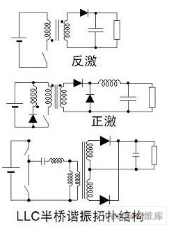
Figure 1: Common LED arrangement
The arrangement of the LEDs and the specification of the LED source determine the basic driver requirements. The main function of the LED driver is to limit the current flowing through the LED under certain operating conditions, regardless of the input and output voltages. The basic working circuit diagram of the LED driver is shown in Figure 2. The so-called "isolation" means that there is no physical electrical connection between the AC line voltage and the LED (ie, input and output). The most common is to use a transformer for electrical isolation. "Non-isolated" does not use high-frequency transformers for electrical isolation.
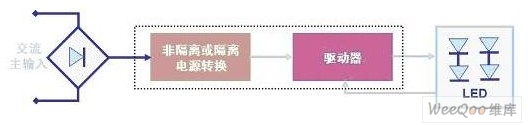
Figure 2: Schematic diagram of the basic working circuit of the LED driver
It is worth mentioning that in the LED lighting design, the AC-DC power conversion and constant current drive can be configured in different configurations:
1) The integral configuration, that is, the fusion of the two, is located in the lighting fixture, the advantages of this configuration include optimizing energy efficiency and simplifying installation;
2) Distributed configuration, ie both exist separately, this configuration simplifies security considerations and increases flexibility.
LED driver can work with constant voltage (CV) output according to different application requirements, that is, the output voltage is clamped under a certain current range; it can also work with constant current (CC) output, and the output design can strictly limit the current; A constant current constant voltage (CCCV) output operation may be used, which provides a constant output power, so the current is determined as the forward voltage of the LED of the load.
In general, LED lighting design needs to consider the following factors:
Output power: related to LED forward voltage range, current and LED arrangement, etc.
Power supply: AC-DC power supply, DC-DC power supply, direct AC power supply
Functional requirements: dimming requirements, dimming methods (analog, digital or multi-level), lighting control
Other requirements: energy efficiency, power factor, size, cost, fault handling (protection characteristics), standards to be followed, reliability, etc.
More considerations: mechanical connection, installation, repair/replacement, life cycle, logistics, etc.
Second, the LED drive power topology
In LED lighting applications with AC-DC power supplies, the power conversion building blocks include discrete components such as diodes, switches (FETs), inductors and capacitors, and resistors to perform their functions, while pulse width modulation (PWM) regulators are used to control Power conversion.
The isolated AC-DC power conversion with a transformer usually included in the circuit includes topologies such as flyback, forward and half bridge. See Figure 3, where the flyback topology is the standard choice for medium and low power applications with power less than 30 W. The half-bridge structure is best suited to provide higher energy efficiency/power density. For transformers in isolated structures, the size of the transformer is related to the switching frequency, and most isolated LED drivers basically use "electronic" transformers.
Figure 3: Common isolated topology
In LED lighting applications using DC-DC power supplies, LED drivers can be used in the form of resistors, linear regulators, and switching regulators. See Figure 4 for a basic application. In the resistive drive mode, the forward current of the LED can be controlled by adjusting the current sense resistor in series with the LED. This drive mode is easy to design, low in cost, and has no electromagnetic compatibility (EMC) problem. The disadvantage is that it depends on the voltage and needs to be filtered. (binning) LED with low energy efficiency.
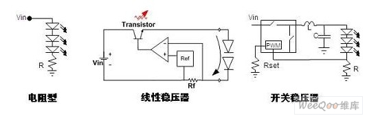
Figure 4: Common DC-DC LED Drivers
Linear regulators are also easy to design and have no EMC issues. They also support current regulation and fold back, and provide an external current set point. The power dissipation problem is insufficient, and the input voltage is always higher than the forward voltage. Voltage, and energy efficiency is not high. The switching regulator continuously controls the opening and closing of the switch (FET) through the PWM control module to control the flow of current.
Switching regulators have higher energy efficiency, are independent of voltage, and can control brightness. Insufficient is relatively high cost, high complexity, and electromagnetic interference (EMI) problems. Common topologies for LED DC-DC switching regulators include Buck, Boost, Buck-Boost, or Single-Ended Primary Inductor Converter (SEPIC).
Where the lowest input voltage under all operating conditions is greater than the maximum voltage of the LED string, a buck structure is used, such as driving 6 LEDs in series with 24 Vdc; in contrast, when the maximum input voltage is less than the minimum output voltage under all operating conditions Boost structure, such as 6 series LEDs driven by 12 Vdc; and the input voltage and output voltage range overlap can be buck-boost or SEPIC structure, such as 12 Vdc or 12 Vac to drive 4 series LEDs However, the cost and energy efficiency of this structure is the least desirable.
The way of directly driving LEDs with AC power has also achieved certain developments in recent years. See Figure 5 for the application diagram. In this configuration, the LED strings are arranged in opposite directions, operating in a half cycle, and the LEDs are turned on when the line voltage is greater than the forward voltage. This structure has its advantages, such as avoiding the power loss caused by AC-DC conversion. However, in this configuration, the LED is switched at a low frequency, so the human eye may be aware of flicker. In addition, LED protection is required in this design to protect it from line surges or transients.
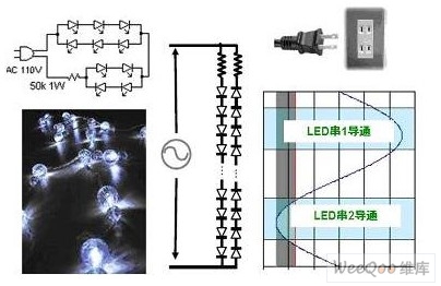
Figure 5: Schematic diagram of direct use of AC driven LEDs
Third, power factor correction
Power Factor Correction (PFC) is mandatory for any power class specified by the US Department of Energy (DOE) ENERGY STAR Solid State Lighting (SSL) specification. This standard applies to a range of specific products, such as recessed lights, cabinet lights and table lamps, where the LED driver power factor for residential applications must be greater than 0.7, and for commercial applications greater than 0.9; however, this standard is a voluntary standard. The European Union's IEC61000-3-2 Harmonic Content Standard specifies the total harmonic distortion performance of lighting applications with powers greater than 25 W. The maximum limit is equivalent to total harmonic distortion (THD) < 35%, while power factor (PF) )>0.94.
While not all countries absolutely mandate improved power factor in lighting applications, some applications may have this requirement, such as utilities that promote commercial applications of products with high power factor in utilities, and utilities. When an organization purchases/maintains a street light, it can also decide whether it is required to have a high power factor (usually >0.95+) according to their wishes.

Figure 6: Schematic diagram of the application circuit of the active PFC
PFC technology includes both passive PFC and active PFC. Passive PFC solutions are bulky and require additional components to better change the current waveform to achieve a power factor of about 0.8 or higher. Among them, in lower power applications of less than 5 W to 40 W, almost the standard choice of flyback topology requires only passive components and minor circuit modifications to achieve a power factor greater than 0.7.
The active PFC (see Figure 6) is typically added to the circuit as a dedicated power conversion section to change the input current waveform. Active PFCs typically provide boost, with a wide input range of 100 to 277 Vac, and a PFC output voltage range of 450 to 480 Vdc. If the PFC section is properly designed, it can provide 91% to 95% energy efficiency. However, with the addition of active PFC, a dedicated DC-DC conversion is still required to provide current regulation.
Fourth, energy efficiency issues
The energy efficiency of LED lighting applications needs to be considered in conjunction with power output. The US Energy Star solid-state lighting specification specifies the energy efficiency of the lighting fixture level, but does not address the energy efficiency requirements of individual LED drivers. As mentioned earlier, LED applications with AC-DC power supplies can use a two-stage distributed topology, so they may be powered by an external AC-DC adapter.
The ENERGY STAR does include specifications for single-output external power supplies. The 2.0 version of the external power supply specification came into effect in November 2008, requiring a minimum efficiency of 87% in standard operating mode and a minimum efficiency of 86 in low-voltage operating mode. %; In this specification, PFC is required when the power is greater than 100 W.
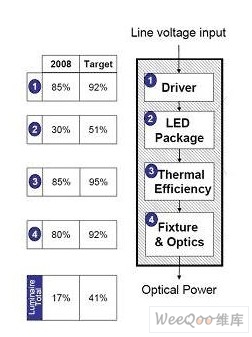
Figure 7: Energy efficiency research and development goals for LED lighting fixtures proposed by the US Department of Energy in the fall of 2008
In LED applications with AC-DC power supplies, providing higher AC-DC conversion energy efficiency involves trade-offs between cost, size, performance specifications, and energy efficiency. For example, using higher quality components and lower on-resistance (RDSon) can reduce losses and improve energy efficiency; lowering the switching frequency generally improves energy efficiency, but increases system size. New topologies such as resonance provide greater energy efficiency, but also increase the complexity of the design and components. If we limit the design to a narrower power and voltage range, it can help optimize energy efficiency.
Five, the drive standard
The LED driver itself is also evolving, with a focus on further energy efficiency, increased functionality and power density. The US "Energy Star" solid-state lighting specification proposes energy efficiency limits at the lighting fixture level, involving specific product requirements including power factor. The requirements of the European Union's IEC 61347-2-13 (5/2006) standard for LED modules powered by DC or AC include:
Maximum safety extra low voltage (SELV) operating output voltage ≤ 25 Vrms (35.3 Vdc)
"appropriate" / safe work under different fault conditions
No smoke or flammable when it fails
In addition, the ANSI C82.xxx LED driver specification is still under development. In terms of safety, it is required to comply with UL, CSA and other standards, such as UL1310 (Class 2), UL 60950, UL1012. In addition, LED lighting design involves product life cycle and reliability issues.
:
Pvc Extension Tube,Flexible Extension Tube,Plastic Extension Tube,Vacuum Cleaner Telescopic Tube
Chaozhong Industrial Co., Ltd. , http://www.zjvacuumcleaner.com