1 Introduction
During the operation of the CCD camera system, there are many data from the job site that need to be collected, processed and recorded in real time. So that the superior management system can keep abreast of the working status of the camera. And the superior management system needs to adjust the camera parameters in real time and issue corresponding instructions, so that the image captured by the camera is better.
The MCS-51 microcontroller contains a programmable full-duplex serial communication interface. The interface circuit not only can transmit and receive data at the same time, but also can be used as a synchronous shift register. The structure of the serial port of MCS-51 MCU consists of three parts: serial port control register, transmission and receiving circuit.
Serial communication is a communication that can transfer binary data bit by bit, so it requires very few transmission lines, and is especially suitable for hierarchical, hierarchical and distributed control systems and remote communication [1]. According to the needs of actual use, the communication between the CCD camera system and the superior management system is completed by the serial port of the single chip microcomputer. This paper introduces the serial communication system in this system.
2 system serial communication system According to the serial data synchronization mode, serial communication can be divided into synchronous communication and asynchronous communication. The system uses synchronous communication. The input and output interfaces of the data are controlled by their own clocks, which are independent of each other and are not synchronized [1].
Since the data input and data output of the CCD camera system are not performed at the same time, the serial communication architecture of the system includes the following parts: a small-chip microcomputer system, a serial data input module, and a serial data output module. Among them, the small-chip single-chip system has a simple structure and mature performance, and will not be described here. Now let's explain the serial port input and serial output module:
This article refers to the address: http://
2.1 Serial Data Input Module The injection of camera parameters is the responsibility of the superior management system. The CCD camera system reads the parameters directly into the small-chip microcomputer system in the camera system through the data bus.
The data input gating signal is connected through the P1 port of the MCU. When the superior management system wants to inject the adjustment parameter command into the CCD camera system, the gating signal is first valid, and the MCU system is ready to receive the data; then, with the cooperation of the clock signal, the data is read one by one and passed through the data. The bus reads parallel data into the microcontroller.
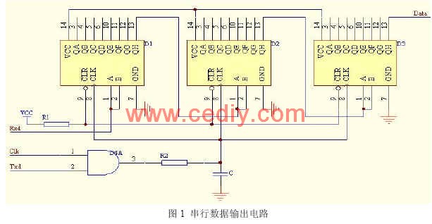
2.2 Serial Data Output Module At each interval, the CCD camera system sends the parameters of the camera system to the higher-level data management system to check if the status of the camera system is normal. The circuit design is shown in Figure 1. In mode 0, the serial data output circuit serially outputs data from the RxD line of the MCS-51 microcontroller through several serial-in and parallel-out shift registers, and serially outputs from the highest bit of the shift register.
3 system serial communication protocol
3.1 System serial communication protocol characteristics Due to the transmission distance and reliability requirements, the communication protocol has the following characteristics [2]:
(1) One-to-one communication method, no handshake process. In communication, the upper management system is the master station and the CCD camera system is the slave station;
(2) In order to effectively recognize camera parameters. The respective command codes are set for each command parameter, but the frame length remains unchanged.
(3) Since the check code is the core of error detection, it is very important to improve the reliability of data transmission, and the parity check mode is simple and feasible. Therefore, the parity check method is adopted to ensure the accuracy of data transmission;
4 system serial communication software implementation
4.1 Communication Protocol Format Description The following describes the specific communication protocol format of this system. The packet structure of the protocol is roughly as follows:
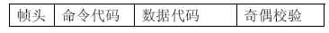
(1) Frame header in order to accurately send and receive serial port data. Set the frame header to OxAA (10101010).
(2) Command code In the communication protocol of this system, the respective command codes are set for each command parameter, and will not be described in detail here.
(3) The data code data code follows the command code, and the user can take 5 bits, 6 bits, 7 bits or 8 bits according to the situation, and the low bit is in the front high position.
(4) Parity parity This byte is calculated according to the usual communication protocol standard. That is: the accumulation of one frame of data except the frame header [3-4].
4.2 Baud Rate of Serial Communication The baud rate is the number of bits of binary digits transmitted per second. The unit is bps (bit per second), which is bit/second. The baud rate is an important indicator of serial communication and is used to characterize the speed of data transmission. The higher the baud rate, the faster the data transfer speed.
Synchronous communication has a high data transfer rate, typically up to 56,000 bps or higher. However, the disadvantage of synchronous communication is that the transmit clock and the receive clock are required to be strictly synchronized.
4.3 Serial communication software flow chart On the basis of fully understanding the user's needs, first determine the system structure, and then determine the software development platform and tools, using the top-down, step-by-step optimization design method to divide the software's functional modules and functional units, Improve the efficiency of software development.
This system uses the serial port mode 0, programming in assembly language. Software flow chart (only includes serial communication subroutine) as shown in Figure 2. 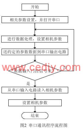
5 Conclusion Programming in assembly language is a more reliable way to achieve serial communication. The communication module is designed with a serial communication protocol with its own characteristics, which effectively solves the communication problem between the data management system and the CCD camera system. Has been successfully applied to a CCD camera system. This design has certain promotion and application value to other types of serial communication systems.
The author of this paper innovates: Using the serial port of the single-chip microcomputer, it is designed as a data input port that is serially connected to and out and a data output port that is serially connected in series. The hardware structure is simple and the performance is reliable. The serial port mode 0 which is less used in communication is used for communication design. .
The LED Indicator is a device that monitors the operation or position of an electrical device with light. The indicator light is usually used to reflect the working state of the circuit (with or without electricity), the operating state (running, outage or test) of the electrical equipment, and the position status (closed or disconnected).
In our company,mainly have eight series(as follow):
AD22-22DS LED Indicator
AD22-4SMD LED IndicatorAD16 LED Indicator
AD22-22MSD Buzzer
AD22-30DS LED Indicator
AD22-DAV Current Voltage Indicator
AD22-DAM Current Indicator
AD22-DVM Voltage Indicator
LED Indicators,LED Indicator Light,LED Indicator Lamp,LED Indicator Bulbs
Ningbo Bond Industrial Electric Co., Ltd. , http://www.bondelectro.com