Abstract: Real-time performance is an important criterion for measuring the performance of CAN fieldbus systems. This paper proposes a driver design scheme that uses the μC/OS-II operating system and I-CAN protocol to improve the real-time performance of the CAN bus system at the application level, and illustrates the design process of the CAN driver layer by layer in a layered manner.
Key words: CAN bus; μC/OS-II; real-time; driver
This article refers to the address: http://
Introduction The CAN bus was developed by Bosch in Germany for automotive applications in 1983. A serial communication network that effectively supports distributed control and real-time control is a fieldbus. The communication distance is related to the baud rate, the maximum communication distance is up to 10 km, and the maximum communication baud rate is up to 1 Mbps. CAN bus arbitration uses the 1l bit (CAN2.OA protocol) and 29-bit (CAN 2.OB protocol) flags, as well as the non-destructive arbitration bus structure mechanism, which can determine the priority of the data block and ensure the highest priority when the network node conflicts. Nodes do not need to wait for conflicts. Any node on the CAN bus can actively send information to other nodes on the network at any time without dividing the primary and secondary, thus achieving free communication between the nodes. At present, the CAN bus protocol has been certified by the International Organization for Standardization, and the technology is relatively mature. It has been widely used in automotive, industrial, high-speed networks and low-cost multi-connection.
μC/OS-II is Jean J. A small embedded operating system developed by Labrosse. It is essentially a priority-based deprivationable kernel, and all tasks in the system have a unique priority level, which is suitable for occasions with strong real-time requirements. This article uses μC/OS-II to design CAN drivers to meet the real-time requirements of the system.
1 CAN node hardware design CAN node is the basic unit distributed in the CAN network for mutual communication, mainly composed of main controller, CAN controller and CAN transceiver. In this design, the basic structure of the node is shown in Figure 1. In a CAN network, an ECU (Electronic Control Unit) refers to a CAN node with full functionality.
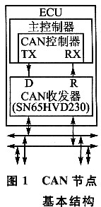
The NPC company's LPC2368 is used as the main controller of the CAN node. The LPC2368 is a RISC processor based on the ARM7TDMI-S core and contains two CAN controllers that are CAN2.0B compliant. Each CAN controller has a dual receive buffer and a tri-state transmit buffer with a fast hardware-implemented search algorithm that supports a large number of CAN identifiers.
The LPC2368 is a 3.3 V device. Although its corresponding CAN transceiver interface pin can withstand 5 V, in order to make the CAN node run more stably, TI's 3.3 V CAN transceiver SN65HVD230D is used here. Use with it. With high input impedance, the SN65HVD230D can support up to 120 CAN nodes on a single bus and is compatible with 5V CAN transceivers. This article focuses on the design of CAN drivers.
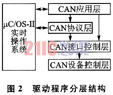
2 CAN driver design overall idea In order to make the software portable and easy to maintain, the CAN driver is written in a layered way. The driver hierarchy is shown in Figure 2. In the figure, the double-headed arrow indicates the data exchange between the real-time operating system μC/OS-II and the CAN driver, and the one-way arrow indicates the upper layer software calls to the lower layer software.
3 CAN device control layer and CAN interface control layer The main task of the CAN device control layer is to initialize the connection configuration between the main controller and the CAN controller, reset the CAN controller, and establish communication between the main controller and the CAN controller. function. Since the LPC2368 integrates the CAN controller internally, the CPU can access all the registers of the CAN controller through the internal APB bus interface, so it is no longer necessary to write the device control driver layer program, which has been completely implemented by hardware.
The main task of the CAN interface control layer is to implement various functions of the CAN controller, such as setting the control mode, transmitting data, releasing the receive buffer, and configuring the acceptance filter. These operations are performed by reading and writing the internal registers of the CAN controller.
The CAN controller initialization program (implemented in the application layer, the functions called internally are also written in this layer) are as follows:
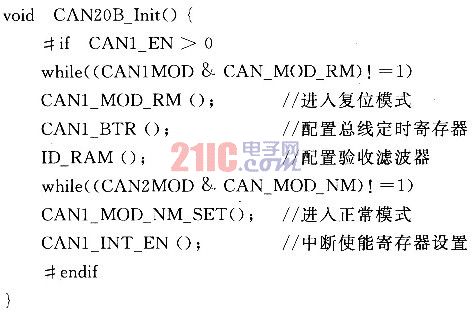
In order to make the program more concise and readable, it can be written in the form of macro definition. E.g:
#define CAN_MOD_RM()CANlMOD |=1
CANlMOD is the mode register of the CAN controller. The lowest position of 1 causes the CAN controller to enter the reset mode. In this mode, all registers of the controller can be written. Other operations on the internal registers of the CAN controller can be found in the technical manual of the LPC2368.
4 CAN protocol layer From the perspective of OSI network model, the field bus network generally implements layer 1 (physical layer), layer 2 (data link layer), and layer 7 (application layer); while CAN fieldbus only The first layer and the second layer are defined, and the two layers are respectively implemented by a CAN transceiver and a CAN controller. The CAN bus does not specify the application layer and is not complete in itself. Therefore, a high-level protocol is required to define the 11/29-bit identifier and 8-byte use in CAN messages. At present, there are some international standard CAN bus high-level protocols, such as DeviceNet protocol and CANopen protocol; however, this protocol specification is more complicated, and it is difficult to understand and develop. For some uncomplicated CAN bus-based control networks, it is not too complicated. Suitable for. This design adopts the simple CAN application layer protocol I-CAN protocol developed by the domestic Zhou Ligong CAN development organization according to the actual application, as the CAN protocol layer of software design. The 29-bit frame identifiers in the ICAN protocol are defined as listed in Table 1.
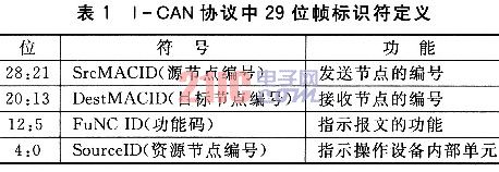
CAN bus arbitration is done bit by bit starting from the highest bit (28 bits) of the identifier. Each transmitter compares the level of the transmitted bit with the monitored bus level: if the same, the unit can continue to transmit; if the transmitted is "recessive" (logic 1) level, the monitored However, it is a "dominant" (logic O) level, then the unit loses arbitration and must exit the transmit state. According to the I-CAN source node number part, it can be seen that the smaller the address number of the node, the higher the priority, and the bus usage right can be preferentially obtained during arbitration. In a CAN network system, the more important a node is, the higher the priority of the assigned address number is. For example, the engine electronic control unit in the vehicle network should have a higher priority than the directional headlight electronic control unit, so as to ensure that important messages are transmitted in time. After the node receives the message, the application parses the message identifier according to the I-CAN protocol and implements its specified function.
5 CAN application layer The CAN application layer implements all the functions of the CAN controller. The CAN device control driver layer, the CAN interface driver layer, and the CAN protocol layer are all in the control of the application layer. The main tasks implemented by the application layer include:
1 Initialize the CAN controller and the global variables associated with the application layer.
2 Write the interrupt service program of the CAN controller.
3 message processing tasks. This task is based on the I-CAN protocol to parse the message and implement the function of the message indication.
4 message sending task. This task stores the unsent packets and automatically sends the message if the send buffer is available.
The procedure for initializing the CAN controller is detailed in Section 3. Since the initialization of the CAN controller is directly linked to the performance of the CAN physical layer and the link layer, the CAN controller can be properly configured only in accordance with the specific application environment.
5.1 Interrupt Service Routine The interrupt service routine is used to determine the type of interrupt of the CAN controller and respond accordingly. The specific procedures are as follows:
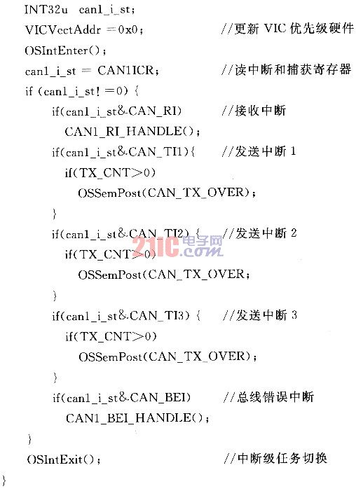
Only the receive interrupt, the transmit interrupt, and the bus error interrupt are described here. Other types of CAN interrupt processing should be specifically designed according to the specific system.
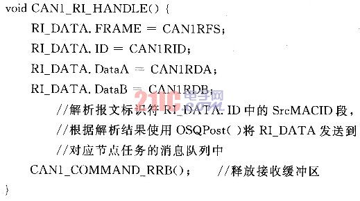
5.1.1 Receive Interrupt The receive interrupt handler CANn_RI_HANDLE() is responsible for receiving the message and sending it to the message queue of the task. The code is as follows:
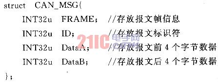
Among them, RI_DATA is the defined structure CAN_MSG variable; CANlRFS, CANlRID, CANlRDA and CANlRDB are registers for the CAN controller to store the received message frame information, identifier and data byte, respectively. The CAN_MSG structure is as follows:
5.1.2 Transmit Interrupt When the Transmit Interrupt Handling Function determines the message to be sent in the message queue of the message sending function through TX_CNT, it sends a semaphore to the message OSSemPost (CAN_TX_OVER) to inform it that it can send the message. If TX_CNT is 0, there is no message to be sent in the message queue, and no semaphore is sent.
5.1.3 Bus Error Interrupt CANl BEI HANDLE() determines the type of error by polling the interrupt and capture registers and recording it for system diagnostics.
Since both CANl_RI_HANDLE() and OSSemPost() are ready to wait for tasks, the system is guaranteed to perform tasks strictly according to priority. The program uses the OSIntEx-it() function to perform interrupt-level task switching, and runs a task with the highest level after executing the interrupt service routine instead of returning the interrupted task.
5.2 Problems faced by the application layer and solutions The following describes the message processing and message sending functions in detail in combination with the actual problems faced by the application layer.
The 1CAN node sets the CAN interrupt to the FIQ interrupt, while the other interrupts are set to IRQ interrupts of different priorities. Since the FIQ interrupt can interrupt the IRQ interrupt, the node can respond to the CAN interrupt as quickly as possible under any circumstances, improving the real-time performance of the system.
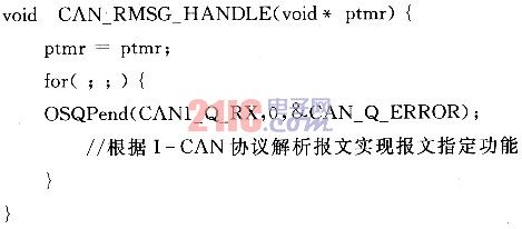
The written CAN interrupt service program should be as short as possible, and the interrupt service task should be put out of the interrupt service program as much as possible without affecting the system performance, so as to exit the FIQ interrupt mode as soon as possible, so that the node can respond to the new interrupt and reduce Interrupt delay in the system. Among them, the receiving interrupt processing is the most occupied node resource. It not only needs to parse the message according to the I-CAN protocol, but also needs to perform the function specified by the message, so it must be executed outside the interrupt service program. The solution is to create a message processing task by the OSTaskCreate() function in μC/OS-II. This task consists of a request message queue function OSQPend() and a message parsing function. The message processing function is as follows:
If you need to send a CAN message, you first need to query whether there is a send buffer available: if it is available, it can be sent directly, without using the message queue as an intermediary, thus improving the efficiency of the program; if both are locked, then calling OSQPost() will The message is sent to the message queue MESSAGE_TX of the message sending function, and the TX_CNT++ operation is performed.
2 In a busy CAN network, the node may not be able to transmit data in time due to the loss of arbitration. Therefore, the data to be sent must be stored, and then sent out when the node obtains the bus usage right. The LPC2368's CAN controller has a three-state transmit buffer that can store up to three messages. If all three buffers are locked (the message is waiting to be sent or is in the process of sending), and another message needs to be sent, an additional buffer is needed to store it first, so that when the node obtains the bus usage rights Send again.
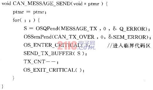
Define an array of pointers, store the first address of the created message data buffer into this array, and then call the OSQCreate() function to create a message queue MESSAGE TX for storing the transmitted message, and finally create it by the OSTaskCreate() function. A task responsible for sending messages. The task consists of a request message queue function OSQPend() and a request semaphore function OSSemPend(). The message sending function is as follows:
The variable TX_CNT records the number of packets in the MESSAGE_TX. The task sends a message to MESSAGE_TX, TX_CNT is incremented by one; the message sending function successfully sends a message, and TX_CNT is decremented by one. In this way, the interrupt service routine can determine whether there is a need to send a semaphore to CAN_TX_OVER according to TX_CNT, reducing unnecessary redundant operations.
Unless there is a more important task in the CAN node task than sending the processed CAN message, in general, the message sending task should have the highest priority in the node task to ensure the real-time performance of the CAN system. .
The 3LPC2368 has a maximum operating speed of 72 MHz and a CAN maximum transfer rate of 1 Mb/s. In general, even if two consecutive messages are received, the CPU is fully capable of processing the first message before receiving the second and second messages, so only one message processing task needs to be established.
There are also nodes that need to complete more complex tasks, such as the Central Control Unit (BSI) in the in-vehicle network. In the all-CAN vehicle network, it connects three networks of the internal network, the body network and the comfort network. As the backbone of the vehicle-mounted network system, the BSI task is heavy. The processing of CAN messages is often interrupted by various interruptions and internal tasks, so it is not guaranteed to process the last received CAN message in time. In addition, because the message queue is configured by first-in-first-out (FIF0) or last-in-first-out (LIFO), when the message queue contains a number of unprocessed messages, the highest priority cannot be taken first. The message is processed. In order to prioritize the packets sent by important devices, an independent packet processing task must be established for each node in the system that has a CAN communication relationship with the node. This task contains a separate message queue, and the higher the priority of the node that sends the message, the higher the priority set by the task. For this reason, the CANl_R1_HANDLE() function should also be modified accordingly. The modified program code is as follows:
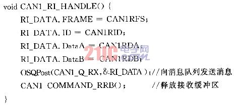
Combined with the arbitration mechanism of the CAN link layer, it is ensured that the node with the higher priority has priority to send the message and is preferentially processed by the receiving node. At this point, the entire context of the CAN driver has been very clear, and the overall process is slightly - editor's note.
Conclusion Based on the μC/OS-II operating system, the CAN driver written for the CAN system with higher real-time requirements is simple and efficient. In different application environments, only the corresponding user code can be added to form a complete CAN driver. program. However, while improving the real-time performance of high-priority nodes, it also reduces the real-time performance of low-priority nodes to a certain extent. Therefore, in engineering applications, the real-time performance of high- and low-priority nodes should be considered according to actual needs.
24V lithium ion battery packs normally drive machines in-doors and out-doors, such as lawn mower, floor cleaner, forklift, yacht, electric trailer, electric scooter, electric tractor and so on. Users also apply it to solar LED light of big power, UPS, and energy storage. FORZATEC technology adopts 8 series of various high-power-density LFP cells and protection circuit boards to ensure the customers to acquire sufficient power supply.
24V Lifepo4 Lithium Battery,Rechargeable 24V Lifepo4 Lithium Battery,Rechargeable 24V Lithium Ion Battery,24V20Ah Lifepo4 Lithium Battery
FORZATEC CO., LIMITED , http://www.forzatec.com