In this article we will describe the compensation issues involved in using the recommended test circuit. If the loop in the test circuit is unstable, it is useless. The output of the test loop of the device under test is always monitored during the test. If the loop oscillates and you don't know, you may report bad results. To make matters worse, you may find it late, and it is even harder to correct the problem at this time.
Self test compensation
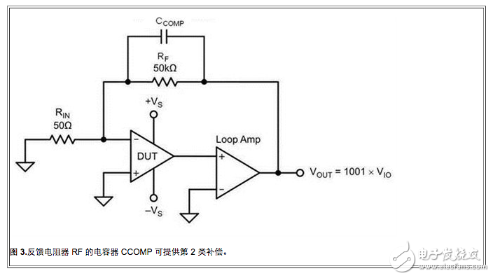
Use large resistor test ![]() A small capacitor is required for each Ib resistor to keep the loop stable (refer to the previous article). Adding this capacitor reduces resistor noise, but care should be taken to fully charge the capacitor before measuring.
A small capacitor is required for each Ib resistor to keep the loop stable (refer to the previous article). Adding this capacitor reduces resistor noise, but care should be taken to fully charge the capacitor before measuring.
Dual amplifier loop compensation
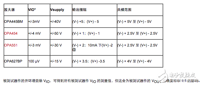
Several op amps are available for loop amplifiers, including the OPA445, OPA454, OPA551, and OPA627BP, but other similar devices are fine. Table 1 lists the important characteristic parameters for any amplifier used for this purpose:
Table 1. Amplifier characteristics required for Class 1 and Class 2 compensation.
If the offset voltage time gain causes the loop amplifier output to enter the rail, you may need a loop amplifier with a larger power supply than the device under test. In this case, it may be necessary to fine tune the final performance of the device under test. For example, if the initial untrimmed offset voltage is 20mV, the loop amplifier needs to be able to support 20V swing. This kind of problem is measuring ![]() It will also appear.
It will also appear.
Referencing the input common-mode range of the null amplifier is an important consideration. Partial integration of the loop amplifier's power supply with the common-mode range must help achieve the rail-to-rail output of the device under test. You can do this by shifting the power of the device under test. It is very convenient to get an extra common mode range in the loop amplifier.
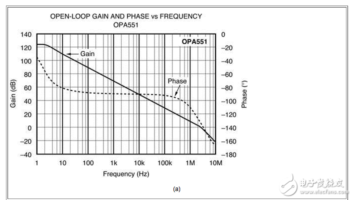
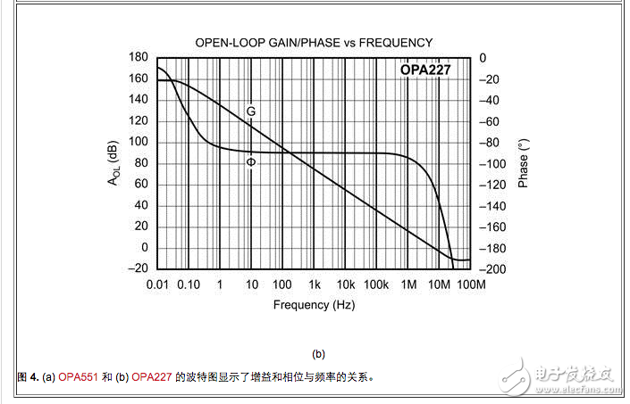
Once the loop amplifier is selected, you need to get the Bode plot of the loop amplifier and the device under test. Figure 4 shows the Bode plot of the OPA551 and OPA227. These Bode plots are typical curves from the product manual. We used the OPA551 as a loop amplifier and the OPA227 as the device under test, as shown in the example in Figure 4.
As can be seen from the Bode plot in Figure 4, the gain bandwidth (GBW) of the OPA551 is 3MHz and the gain bandwidth of the OPA227 is 8MHz. The OPA551 has a DC gain of approximately 125dB and the OPA227 has a DC gain of approximately 160dB.
Type 1 compensation method
With the loop diagram of the loop amplifier and the amplifier being tested, you can plot the Bode plot representing the test loop. You can use a logarithmic ruler to manually draw a Bode plot to determine the compensation capacitor value. This method is reliable, but using a spreadsheet can greatly simplify the task. Once the spreadsheet has been set up, it is easy to determine the compensation value for any new part.
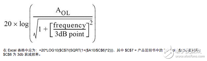
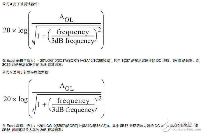
Several types of formulas are required for Class 1 compensation. The tested device uses Equation 1:
Equation 1 should create a curve that matches the open-loop gain curve in the product description of the device under test. You can determine the curve by adjusting the 3dB point to get the correct bandwidth.

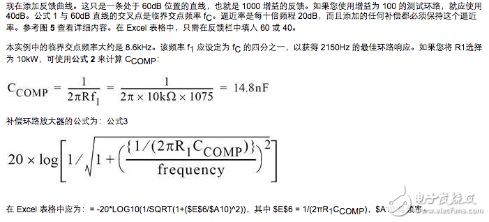
In a dual amplifier loop, the output of the device under test can be connected as an input to a loop amplifier. Therefore, these op amps can be cascaded. The gain is the product of the gains of the two amplifiers. In decibels, the gain product is the summation. Since we are in decibels, we should add Equation 1 and Equation 3 to get the sum of the two amplifiers.
In the Excel table it should be: =B10+C10
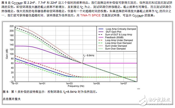
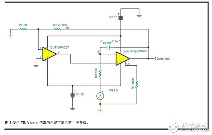
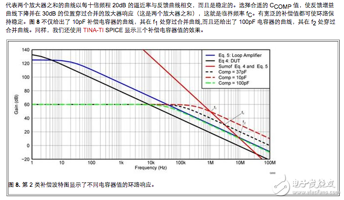
The circuit in Figure 6 simulates a Class 1 loop response.

We ran transient simulations for C1=2.2nF, 7.7nF, and 22nF, respectively. The loop control input is changed from 0V to 10V, as is the case when measuring the operational amplifier Aol. Figure 7 shows the resulting output waveform. In all three cases, the loop is very stable, but there is significant ringing when it is less than 7.7nF. Therefore, the loop is underdamped. When the capacitor value is higher than 7.7nF, the loop is overdamped. When the capacitor is 22nF, the loop has not stabilized within 1.0ms. It will eventually stabilize, but it will consume more test time.
High Power IR LED.
We supply High power IR LED products with difference power, such as: 0.5W 940nm High Power IR LED, 1w 940nm High power IR LED, 2W 940nm High power IR LED, 2w 940nm High power IR LED, 3W 940nm High power IR LED, 0.5W 850nm High power IR LED, 1w 850nm High power IR LED, 2W 850nm High power IR LED, 3W 850nm High power IR LED and so on.

In addition, we also add the lens on the top of SMD LED , which can make the SMD LED have an angle like those Thought-hole LED, which we called it 'IR Domed LEDs'.
For example: 850nm High power IR LED with 30 degrees, 850nm High power IR LED with 60 degrees, 850nm High power IR LED with 90 degrees, 940nm High power IR LED with 30 degrees, 940nm High power IR LED with 60 degrees, 940nm High power IR LED with 90 degrees, etc.We also can customize the mold of ledns as you needed angle.

We produce and sell High power IR LED, which is with the wavelength from 680nm-1550nm.
In this category, we mainly introduce the two kinds of wavelengths: 940nm IR LED and 850nm IR LED. These two wavelengths are the most commonly used wavelengths in infrared monitoring. They all can be used to monitor products.
Then what is the difference between 940nm and 850nm?
940nm infrared LEDs are totally invisible to the naked eye, which means you can't see whether the 940nm working or not. Unless you watch it through some device(like phone's camera), which will show some purple or white color light.
The 850nm infrared LEDs have a very slight reddish when it's working, which means you can see if the 850nm LED is working.
Under the same power, radiation intensity of 850nm will be higher than the 940nm. Of course, 940nm also has its own unique advantages. It is the naked eye that is indistinguishable from work or from work, therefore, its application has been widely used in many special markets in the modern era.
High Power IR LED
High Power IR LED, High Power IR LED warranty, 3w High Power IR LED, 940nm High Power IR LED
Shenzhen Best LED Opto-electronic Co.,Ltd , https://www.bestsmd.com