This system is mainly used for the detection of the amount of side slip of automobile wheels. In order to ensure steering straight line without lateral slip of the wheel rolling is required camber and the toe proper fit of the front wheel, when the outer wheel toe-in and camber angles match is not the time, the wheels may not be pure rolling in the straight running, The side slip phenomenon occurs. When this slippage phenomenon is too severe, it will destroy the attachment conditions of the wheels, lose the ability to orientate, cause traffic accidents and cause abnormal wear of the tires. The magnitude and direction of the amount of lateral slip can be detected with a vehicle wheel slip test stand.
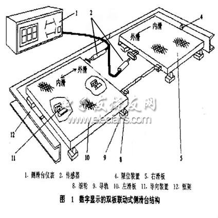
Structure of side sliding table:
System hardware configuration:
2 displacement sensors
2 groups of photoelectric switches
Analog input module
Switch input module
Working principle of the system:
When the wheels step on the side slide, the first group of photoelectric switches are turned off (the photoelectric switch is normally open when not blocked), and when leaving the side slide, the second group of photoelectric switches are turned off, and the side slip of the wheel is recorded at this time. The test of a group of wheels is completed. The wheels step on the side skateboards in sequence and record the amount of side slip as described above to complete the side slip test of the entire vehicle.
Functional structure diagram:
System functions:
Automobile positioning: The system provides three different automobile positioning systems, which are single-axle positioning, double-axle positioning and multi-axle positioning. Among them, multi-axle positioning needs to detect the amount of side slip of 6 groups of wheels.
System settings: You can set the upper and lower limit alarm values ​​for the amount of side slip, the length of the skateboard, and the current trademark of the vehicle under test.
Customer management: able to record and modify information of detected vehicles and support printing.
1.ANTENK Flexible Printed Circuit (FPC) and Flexible Flat Cable (FFC) connectors are ZIF (zero insertion force) and LIF (low insertion force) connectors designed to provide a fast, easy, reliable method to make a connection of flexible printed circuits to a PCB. Adam Tech`s special contact design completely preserves conductor integrity by eliminating all wiping action while making connection. Flex circuitry enters the connector and the connector cap is pressed down to capture the flex circuit producing a stable, high pressure connection. Raising the cap releases the pressure for exchange or replacement of circuitry. This series includes single and dual row versions in thru-hole or SMT mounting in vertical or horizontal orientations.
2.Our products are widely used in electronic equipments,such as monitors ,electronic instruments,computer motherboards,program-controlled switchboards,LED,digital cameras,MP4 players,a variety of removable storage disks,cordless telephones,walkie-talkies,mobile phones,digital home appliances and electronic toys,high-speed train,aviation,communication station,Military and so on


FFC Connector Range Available as:
0.3,0.5, 0.8, 1.0,1.25, 2.54mm connector pitch
Surface mount
Side and Top entry
Side entry parts - Top and bottom contact options
ZIF (Zero Insertion Force)
Slide and flip lock actuator styles
Specifications:
Material And Finish:
Insulator: LCP
Lock: PPS
Insert Spring:Phosphor Bronze,
Matte Tin Plated
Solder Platten Area:Phosphor
Bronze,Matte Tin Plated
Voltage:500 V AC(rms)/DC
Current:0.5 A AC(rms)/DC
Contact Resistance:20 mΩ max(initial)
Insulation Resistance:800 MΩ min
Operating Temp:-20°-85°
Fpc Connector,Fpc Cable Connectors,Ffc Cable Connectors,Pitch Fpc Connector,Surface mount FPC/FFC Connectors,Top entry FFC Connectors, Side entry FFC Connectors
ShenZhen Antenk Electronics Co,Ltd , https://www.antenk.com