In the process of using electrical meters, there are often problems that are easily overlooked, and these problems sometimes cause the instrument to be inaccurate or damaged. To this end, this article describes the matters that should be noted in the use of several electrical measuring instruments.
1 pointer multimeter is used to measure current, voltage, resistance and other multi-meter instruments. In use, when measuring AC voltage, do not misplace the gear. If the gear position is changed, it is easy to burn out the resistance of other gears, and even the head coil is blown. When measuring current, if you don't know how much current, it is best to set the transfer switch to the maximum current position, so that you can change from the big to the small to the required range. Otherwise, the high current will put the small current range resistance. Burn out; when measuring current and voltage, the deflection of the pointer should be more than half of the full deflection; when measuring the resistance, the resistance should be as close as possible to the center of the scale. When testing transistor parameters with ohms, Rx100 or Rx1K should normally be selected. Otherwise, the test transistor may be damaged due to excessive test current (in R × 1) or when the voltage is too high (in R × 10K). It is strictly forbidden to measure the resistance when the measured resistance is charged. Otherwise, the voltage on the measured resistance will not only seriously distort the measurement result, but may even burn out the meter. Switch the current and voltage range, and do not carry it under power, so as not to damage the switch. After the multimeter is used, the switch should be turned to the highest level of the AC current, thus preventing accidents due to carelessness in the next measurement.
2 Insulation resistance measuring instrument is also called megohmmeter or insulated shaker. It is a meter for measuring the insulation resistance of electrical equipment. It is mainly composed of an alternator, a rectifying voltage doubler circuit and a magnetoelectric wattage meter (head). Although the generator capacity of the megohmmeter is not large, the voltage is still high, especially before measuring the capacitive insulation with large capacitance, the object to be tested should be fully discharged. Because there is an insulator between the two conductors, it is equivalent to a capacitor. The DC voltage is added between the two conductors for a period of time to store a part of the electric energy. The larger the electric capacity, the more life-threatening people will be in danger. For example, when measuring the insulation resistance of a cable, the core and sheath of the cable are equivalent to a large capacitor. When shaking with a megohmmeter, add a high voltage to both ends. After the measurement, immediately ground one end of the cable to discharge, otherwise the high voltage will easily reverse the diode and damage the megohmmeter.
When measuring with a megger, the electrical connection between the device and the outside world should be completely removed, so as to avoid the measurement and the connection between the connected part and the device itself.
The handle speed of the megohmmeter should be the rated speed of 120r/min. Do not flicker and slow down, causing the output voltage to be unstable and causing misalignment.
The insulation resistance varies with the length of the measurement time. This is because the dielectric absorption of the insulating material consumes the charging current, which is generally based on readings greater than 15 s. When encountering a sample with a large capacity, it should be taken after the pointer is stable after 1 minute. When measuring the absorption ratio, the reading should be taken strictly according to the specified time.
The megger should be handled lightly and placed in a horizontal position during use. If the tilting is used, the mechanical balance of the Eurometer will change and an additional error will be generated. The friction of the moving part will become larger and the error will become larger. Electrician's house
3 grounding resistance tester is also called grounding shaker. It is used to measure the grounding resistance value of the grounding body of the electrical equipment. It is mainly composed of a hand-cranked generator, a current transformer, a potentiometer, a potential auxiliary pole, a current auxiliary pole, etc., and the magnitude of the grounding resistance value is measured by the compensation method. Before measuring, the instrument should be leveled, then zeroed, so that the pointer is on the red line, and the ground object is connected with E. The potential probe P and the current probe C are grounded into the ground 20 cm apart from each other in a straight line. Place the Magnification Scale at the maximum magnification. In the process of measuring the grounding resistance, when the galvanometer is close to equilibrium, the engine crank speed should be increased to 150r/min.
When the measurement dial is less than 1, the override switch should be placed in the smaller first gear and then re-measured.
When measuring the grounding resistance less than lΩ, the two E-terminal joints should be opened and connected to the grounding body to be tested with wires, eliminating the wiring resistance and contact resistance.
When measuring the grounding resistance of the grounding grid of multiple grounding points, take two to three measuring points and take the average value to eliminate the contact resistance of different measuring points, the position of the instrument, the different positions of the probe, etc. error. Do not measure when there is lightning or when the object is charged.
4 clamp meter is the card meter, mainly used to measure the current of the wire. It consists of a magnet, a moving coil, and a measuring resistor. When measuring the wire current, the two clip heads should be closed, and the wire to be tested should be clamped in the middle. Do not point to either side or lean against the card table. Otherwise, the indication value will be inaccurate. The measuring resistance and magnet in the clamp meter are affected by the current of the conductor and the magnetic field around the current of the conductor. The time is long, and the current value indication value will be out of tolerance. Therefore, the weekly inspection should be performed on time. A multi-purpose clamp meter is composed of a clamp-type current transformer and a multimeter. When the two parts are combined, it is a clamp-type ammeter; when the clamp-type transformer is dialed out, it can be used as a multimeter alone, it should be noted that Table current file amperage has been greatly reduced,
Do not press the current current measurement current value at the current level. Otherwise, the meter will be burned out immediately.
Before using the clamp meter, wipe the oil on the meter jaws and check that the range switch is in the proper position. If the measured object is unknown, turn the range switch to the maximum limit and then select the appropriate limit. The pointer gets the maximum deflection; when changing the range, the test pen should leave the test circuit.
5 When the digital multimeter is in use, in addition to the matters related to the above pointer multimeter, the following matters should be noted:
5.1 The symbol next to the test pen socket is to remind the tester not to make the input voltage and current exceed the specified value, so as not to damage the internal circuit.
5.2 The function switch should be turned to the correct position before use.
5.3 Before measuring, if the voltage range is unknown, the function switch should be placed in the high range and gradually lowered.
5.4 When only the highest position "1" is displayed, it indicates that the range has been exceeded and should be increased by one step.
5.5 When measuring high voltage, special care should be taken to avoid contact with ultra-high voltage circuits (such as accelerating electrodes of cathode ray tubes).
5.6 When the maximum current is 200mA, insert the black test lead into the COM jack and the red test lead into the A jack. If the 10A file is measured, move the red pen to the 10A jack.
5.7 If only "1" is displayed, it indicates an open state or a start state.
5.8 When detecting the resistance in the circuit, it must be determined that the circuit under test has turned off the current, and at the same time, the capacitor has been discharged.
5.9 Some devices may be damaged by the current applied when measuring resistance. Table shows the current and voltage values ​​of each gear.
5.10 Insert the capacitor to be tested into the capacitor socket (not the test pen jack) and pay attention to the polarity.
5.11 To ensure the accuracy of each range measurement, when accessing the capacitor, the near zero knob should be adjusted to read “0000â€.
5.12 When measuring large capacitors, it is necessary to take a long time to obtain a stable reading.
5.13 The circuit under test must check the continuity of the power supply. Failure to do so will result in incorrect judgment or damage to the internal wiring.
The 6 bridge is used to measure the resistance. Its head, that is, the pointer of the galvanometer can be locked, and should be locked as much as possible. Otherwise, it is easy to break the galvanometer hanging wire (there are two hairs) because it is shaken back and forth. If the sensitivity of the polar flow meter is found to be low, the battery should be replaced; some galvanometers are equipped with a 9V battery. When the battery is poorly connected or has no electricity, it will affect the indication value of the bridge, and the tolerance will be severe. Therefore, it is used. Before, it is best to check the battery.
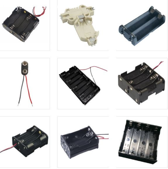
Antenk Battery Holders, Battery Snaps an Mobile battery connectors are designed to create connections and contain batteries in electronic equipment. This series includes battery holders and coin cell holders for AAA, AA, C, D, 9V and lithium coin cells. Antenk produces this series in a variety of terminations such as through hole PCB leads, SMT leads, wire leads and solder lugs. Custom lead lengths on wire configurations are also avaialble. Our superior retention holders are molded of UL-94V0 or UL-94HB material with spring steel contacts and perform extremely well under normal or adverse environment conditions.
Antenk offer a large range of battery and coin cell holders and battery contacts for various mounting requirements.
Our battery clips, contacts & holders are designed with leading edge technology in mind, to accommodate all major manufacturers` batteries.
Available in a wide range of materials and mounting styles including SMT, THM & off board.
Some of the applications include : Telecommunications, memory hold, emergency power systems, personal medical monitoring devices.
Battery Holders

Antenk battery holders rely on continuous innovation.
Every year we continue to innovate and create not only new types holders for new kinds of batteries, but also new types of holders for common batteries. Our award-winning designs have been used in all types of projects around the world, and they have been everywhere from under the sea to outer space. No matter what size and shape battery holder is needed, we can provide a solution. Our standard line includes over 250 different battery holders, with enough variations to suit most applications. We also have a long history of delivering custom battery holder solutions, which we optimize to perfectly suit the the needs of our clients.
Specialized Knowledge
Designing the best battery holders requires the best industry knowledge. At Antenk, we have over 15 years of battery holder design experience. We know what works and what doesn't, and we thoroughly test our newest designs to ensure they meet our rigorous quality standards. Understanding batteries and how they vary among brands, the requirements of modern electronics manufacturing practices, and how electronics consumers operate battery holders are all examples of the specific knowledge we apply during our battery holder design process.
Battery Holders by Type of Battery
1/2AA | 1/3N | 223A | 23A | 9V | AA | AAA | AAAA | C | CR123A | CR2 | CR2/3A | CR2N | D | Li-ion 18650 | N | Other Sizes
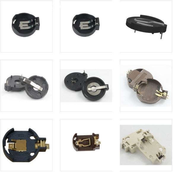
Coin Cell Battery Holders

We have created a wide variety of coin cell battery holders for use in all types of devices, and from handheld medical devices to server motherboards we have solutions for any application. The ever increasing types, sizes, and sheer number of devices which use coin cell battery holders have been keeping us busy, and we have a similarly increasing selection of coin cell battery holder designs. After all, the perfect coin cell battery holder for a handheld medical device is going to be vastly different from the one for a server motherboard.
Unique Coin Cell Battery Holders
Antenk has pioneered a large number of new styles of coin cell battery holders to suit the various needs of the electronics industry. Our Verticals are an excellent way to save space on a crowded board, while our Minis can save almost 3 mm in height above the PCB over traditional coin cell battery holders. Gliders are an excellent upgrade over coin cell retainers, offering more reliable connections while also having simple, tool-less battery replacements. Our newest technology is Snap Dragon, which adds a snapping cover to the traditional style of coin cell battery holders for increased reliability.
Coin Cell Battery Holders by Size of Cell
191 | 335 | A76 | CR1025 | CR1216 | CR1220 | CR1225 | CR1620 | CR1632 | CR2016 | CR2025 | CR2032 | CR2320 | CR2325 | CR2330 | CR2335 | CR2354 | CR2420 | CR2430 | CR2450 | CR2477 | CR3032 | Coin Cell | F3 iButton | F5 iButton | LR1120 | LR44 | ML414 | SR512SW | SR60 | V80H or CP1654 | iButton | BR1025 | BR1216 | BR1220 | BR1225 | BR1620 | BR1632 | BR2016 | BR2025 | BR2032 | BR2320 | BR2325 | BR2330 | BR2335 | BR2420 | BR2430 | BR2450 | BR2477 | BR3032 | Other Sizes
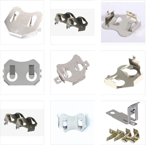
Coin Cell Retainers

Coin cell retainers are simple metal contacts that both electrically connect coin cells and hold them in place, while taking up minimal additional space on the PCB. They feature nickel-plating, and since most coin cells have nickel shells this helps to prevent galvanic corrosion, an electrochemical process that can damage dissimilar metals that are in electrical contact. Our retainers are always designed with automation in mind, and can be easily picked and placed, with both through hole and surface mount retainers available for most coin cell sizes. Combining the ease of automation with the low cost of Antenk's retainers, it is no wonder they are such a popular product.
Coin Cell Retainers by Size of Cell
191 | 335 | CR1025 | CR1216 | CR1220 | CR1225 | CR1632 | CR2016 | CR2032 | CR2320 | CR2325 | CR2330 | CR2354 | CR2430 | CR2450 | CR2477 | F3 iButton | F5 iButton | LR1120 | LR44 | ML414 | SR512SW | SR60 | V80H or CP1654 | BR1025 | BR1216 | BR1220 | BR1225 | BR1632 | BR2016 | BR2032 | BR2320 | BR2325 | BR2330 | BR2450 | BR2477 | Other Sizes
Circle Connector,Battery Holders connector,Battery Contacts,Battery Holders,Battery Clips,Battery Contacts​,Battery Enclosures ,Coin Cell Battery Holders ,Cylindrical Battery Holders Contacts, Clips, Holders & Springs
ShenZhen Antenk Electronics Co,Ltd , https://www.atkconnectors.com