Professor Zhou Ligong's new book "Programming for Ametal Frameworks and Interfaces (I)" provides a detailed introduction to the AMetal framework. By reading this book, you can learn advanced software design principles and development ideas for interface programming. Focusing on your own "core domain," you can change your programming thinking and achieve mutual progress between the company and the individual. Authorized by Professor Zhou Ligong, from now on, the Zhiyuan Electronic Public Number will serialize the content of the book, and is willing to share it with readers.
The ninth chapter is about the BLE & Zigbee wireless module. The content of this article focuses on section 9.2: Zigbee Core Board.
9.2 Zigbee Core Board
The AW824P2EF core board is developed by Guangzhou Zhiyuan Electronics Co., Ltd. based on LPC824 + JN5161 to support Fastzigbee networking protocol and user secondary development. JN5161 is a Zigbee chip provided by NXP Semiconductors, operating in the IEEE 802.15.4 standard ISM frequency band (2.4–2.5 GHz). One of the biggest features of this module is its complete software and hardware ecosystem, allowing it to be quickly applied in industrial control, data acquisition, agricultural control, mining personnel positioning, smart home, and remote control applications.
>>> 9.2.1 Product Introduction
The key features of the AW824P2EF core board include:
- Operating voltage: 2.1V ~ 3.6V
- Maximum transmission power: 20dBm
- Maximum receiving sensitivity: -95dBm
- Integrated Zigbee serial port transparent transmission
- ARM Cortex-M0+ processor with 8KB SRAM and 32KB Flash, supporting 12-bit ADC, SPI, I2C, and UART.
The AW824P2EF core board integrates the complex communication protocols of wireless products into the built-in MCU, significantly simplifying the development process of wireless products. Users can configure and send or receive data through the serial port. The board has 35 pins, with the pin distribution shown in Figure 9.6 and the pin function description in Table 9.6.
Table 9.6 AW824P2EF Core Board Pin Function Description
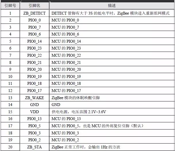
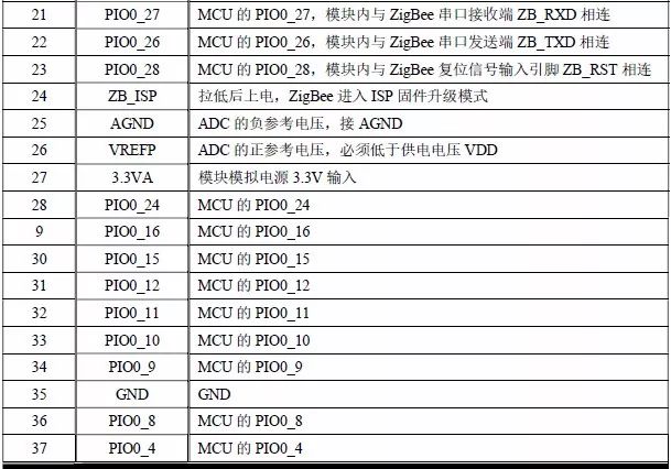
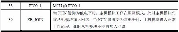
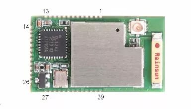
Figure 9.6 AW824P2EF pinout diagram
To facilitate rapid development, the serial port 1 (PIO0_26 and PIO0_27) of the LPC824 is connected to the serial port of the built-in Zigbee chip in the AW824P2EF, and PIO0_28 is connected to the reset pin of the ZM5161. See Figure 9.7 for details. When using the secondary development of the AW824P2EF, the PIO0_26 of the LPC824 needs to be configured as the serial port RX function, and the PIO0_27 as the serial port TX function.
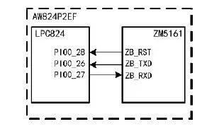
Figure 9.7 Schematic diagram of hardware connection
ZB_RST is the reset pin of the ZM5161. When the PIO0_28 pin outputs a low-level signal lasting more than 1μs, the core board can be reliably reset.
In the AW824P2EF, the Zigbee core board defaults to the long-term industrial application experience of Guangzhou Zhiyuan Electronics Co., Ltd., which is a self-developed Zigbee protocol stack suitable for various industrial applications: Fastzigbee. To distinguish it from the original chip JN5161, the Zigbee module is named ZM5161.
>>> 9.2.2 Network Application
Supporting not only the Fastzigbee protocol, but also other multi-industry wireless protocol stacks such as Zigbee Pro, Zigbee Pro Home Automation, Zigbee Pro Smart Energy, Zigbee Pro Light Link, Zigbee RF4CE, and JenNet-IP. The AW824P2EF Zigbee module runs the Fastzigbee protocol stack by default. Fastzigbee has the following characteristics:
- Fast startup, response, and data transmission efficiency
- Network capacity reaches up to 65,535 terminal nodes
- Low power consumption of the terminal node (as low as 100nA)
- Support for multi-level relay functions, with self-adjusting and self-repairing network capabilities
- Support for multiple remote I/O and remote ADC, with flexible address modification
- Larger link budget
Using the robust Fastzigbee network transparent transmission protocol, the ZM516X module can construct various network topologies. Its main features are strong practicality, high transmission efficiency, stable performance, simple secondary development, and flexible engineering deployment. The Fastzigbee network topology is shown in Figure 9.8.
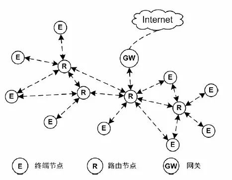
Figure 9.8 Fastzigbee network topology diagram
The terminal node of Fastzigbee is responsible for data acquisition from the sensing device, typically battery-powered and intermittent operation, requiring low power consumption. The routing node is responsible for signal relaying, especially when the terminal node cannot directly reach the gateway node. The routing node also provides multiple signal paths to ensure reliable transmission. The gateway node uploads data collected by the terminal node to the cloud server, using either a wired Ethernet or wireless 3/4G network for data transmission. There are several important parameters to configure for the Fastzigbee network.
Channel number
The channel number determines the radio frequency used by the Zigbee network. Zigbee operates in the 2.4GHz (global popular), 868MHz (popular in Europe), and 915MHz (popular in the US) bands. The 2.4GHz band uses a frequency range from 2405MHz to 2480MHz, divided into 16 channels, numbered from 11 to 26, with a center frequency interval of 5MHz. All nodes in the same Zigbee network must operate on the same channel. By distributing two different Zigbee networks on different channels, they can be physically isolated, eliminating wireless interference.
2. Node type
The Fastzigbee network divides Zigbee nodes into two types: terminal nodes and routing nodes. Terminal nodes perform specific functions and need to sleep, while routing nodes relay signals. If the signal between terminal nodes is unreachable, routing nodes can be added to increase the wireless transmission distance. The Fastzigbee network is peer-to-peer, with all nodes able to send and receive data without a coordinator, making the network more complete, simple, and stable.
3. PanID
PanID is the network ID of Zigbee, distinguishing two different networks. Unlike channel numbers, PanID only logically distinguishes networks. Two different PanID networks working on the same channel can still cause mutual interference.
4. Network address
All nodes under the same Zigbee network have a unique 16-bit address identifying each node and addressing the data to be sent and received.
5. Data transmission mode
Zigbee data transmission includes unicast and broadcast modes. Unicast specifies a target network address, and only the node at that address receives the data. Broadcast sends data to all nodes in the same network.
>>> 9.2.3 Zigbee Initialization
The AMetal platform already supports the ZM516X module, allowing users to directly configure and send/receive data using corresponding APIs. Initialization must be completed before using any function. The function prototype (am_zm516x.h) is:
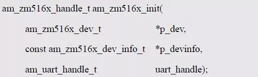
This function retrieves the instance handle of the ZM516X module, where p_dev is a pointer to an am_zm516x_dev_t instance, p_devinfo is a pointer to an am_zm516x_devinfo_t instance, and uart_handle is the serial port handle for communication with the Zigbee module.
Instance
An example of defining the am_zm516x_dev_t type (am_zm516x.h) is as follows:

Where g_zm516x_dev is a user-defined instance, whose address is passed as p_dev.
Instance information
Instance information mainly describes the information related to the Zigbee module. The definition of the type am_zm516x_devinfo_t (am_zm516x.h) is as follows:
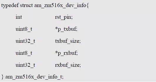
Where rst_pin represents the reset pin of the module, used to reset the Zigbee module when needed. In the AW824P2EF, the Zigbee's reset pin ZB_RST is connected to PIO0_28 of the LPC824, so the value of rst_pin should be assigned to PIO0_28.
To improve data processing efficiency and prevent data loss during transactions, the Zigbee module requires a buffer for data buffering. The buffer size is specified by the user, typically set to 256 bytes. p_txbuf and txbuf_size describe the first address and size of the transmit buffer, while p_rxbuf and rxbuf_size describe the first address and size of the receive buffer. For example, define a 256-byte buffer for sending and receiving:
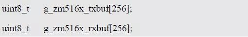
Where g_zm516x_txbuf[128] is a user-defined array used as a send buffer, with its address (g_zm516x_txbuf or &g_zm516x_txbuf[0]) as the value of p_txbuf in the instance information, and the array size as the value of txbuf_size. Similarly, g_zm516x_rxbuf[256] acts as a receive buffer, with its address as the value of p_rxbuf and the array size as the value of rxbuf_size. Based on this, the instance information can be defined as follows:
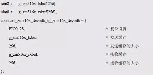
Where g_zm516x_devinfo is a user-defined instance information, whose address is passed as p_devinfo.
UART handle uart_handle
If USART2 of LPC824 is used to communicate with ZM516X, the UART handle is obtained via the USART2 instance initialization function am_lpc82x_usart2_inst_init() of LPC82x, which is:

Example handle
The return value of the ZM516X initialization function am_zm516x_init() is the handle of the ZM516X instance, used as the argument to the zm516x_handle parameter of other function interfaces. Its type am_zm516x_handle_t (am_zm516x.h) is defined as follows:

If the return value is NULL, the initialization fails; otherwise, a valid handle is returned. Based on modular programming, the definitions of instances, instance information, etc., are stored in the ZM516X configuration file (am_hwconf_zm516x.c), and the instance initialization function interface, source file, and header file are extracted through the header file (am_hwconf_zm516x.h). Program examples are detailed in Listings 9.34 and 9.35.
Listing 9.34 ZM516X Instance Initialization Function Implementation (am_hwconf_zm516x.c)
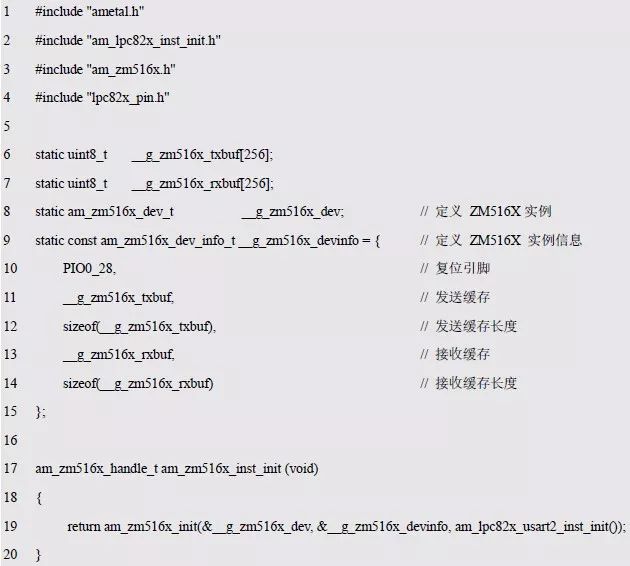
Listing 9.35 ZM516X Instance Initialization Function Declaration (am_hwconf_zm516x.h)

Subsequent use of the parameterless instance initialization function to get the ZM516X instance handle:

>>> 9.2.4 Zigbee Configuration Interface
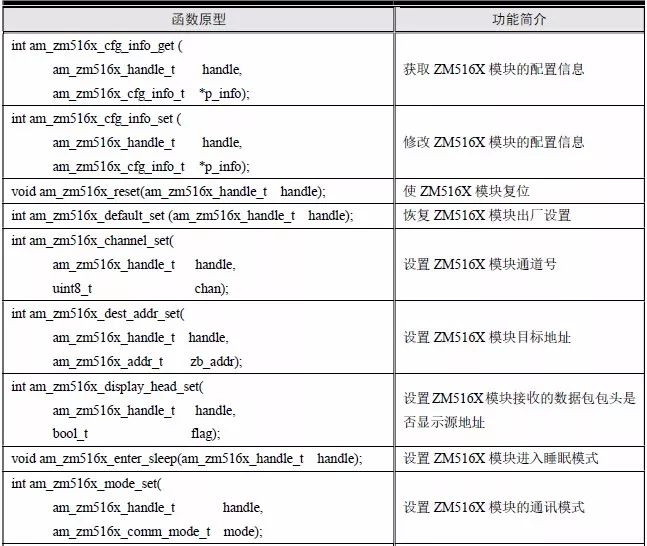
AMetal provides 10 ZM516X module configuration-related interface functions, allowing users to directly configure the Zigbee module. These functions are listed in Table 9.7.
Table 9.7 ZM516X Module Configuration Interface Functions
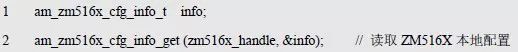
1. Read Local Configuration
This function reads the current permanent configuration parameters. The function prototype is:
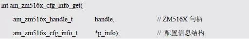
Where p_info is a pointer to obtain configuration information, and am_zm516x_cfg_info_t is a structure containing all permanent configuration parameters of the ZM516X module. Details are in Listing 9.36.
Listing 9.36 ZM516X Permanent Configuration Information Structure
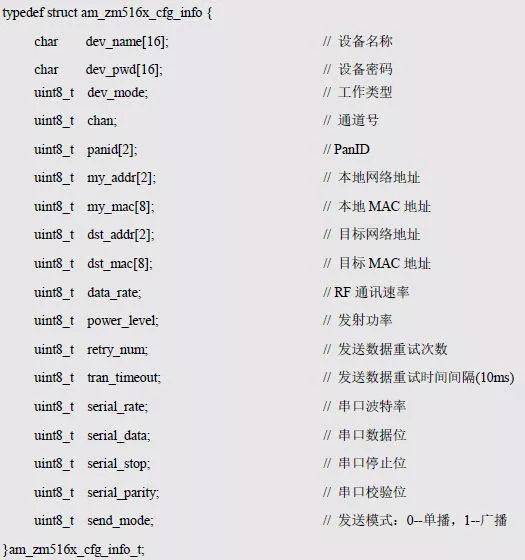
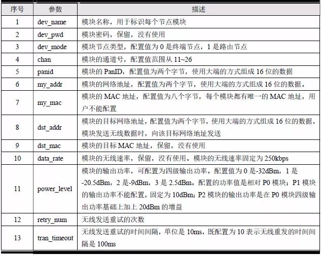
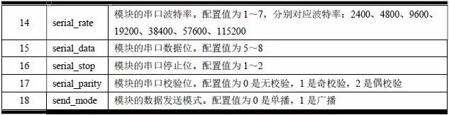
A detailed description of each parameter is given in Table 9.8.
Table 9.8 Description of Permanent Configuration Parameters of the ZM516X Module
See Appendix 9.37 for a sample program for reading the ZM516X local configuration.
Listing 9.37 Reads the ZM516X Local Configuration Sample Program
2. Modify Local Configuration
This function modifies the current permanent configuration parameters. The modified configuration will not be lost after power failure. The function prototype is:
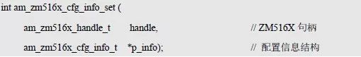
Where p_info is a pointer to the configuration information. After execution, if the configuration is to take effect, the module reset function must be executed to reload the new configuration parameters. A sample program for modifying the local configuration is in Listing 9.38.
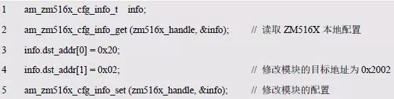
Listing 9.38 Modifying the ZM516X Local Configuration Sample Program
3. Module Reset
This function controls the ZM516X module to generate a hardware reset. The function prototype is:

The reset function allows the user to perform a reset operation on the module. If the user uses the am_zm516x_cfg_info_set() function to modify the configuration, the module reset function must be executed to reload the new parameters after the module is reset. The sample program for module reset is detailed in Listing 9.39.
Listing 9.39 Module Reset Sample Program

4. Restore Factory Settings
This function restores the permanent parameters of the ZM516X module to factory defaults. The function prototype is:

The sample program for module factory reset is detailed in Listing 9.40.
Listing 9.40 Factory Reset Sample Program

5. Set Channel Number
This function temporarily changes the channel number of the ZM516X module during system operation. The function prototype is:
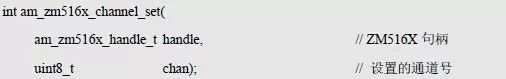
The channel number set by this function is only temporarily valid. After the module restarts (power-down restart or software reset), the setting will be lost and the module will reuse the channel number from the permanent parameter configuration. The sample program for setting the module channel number is shown in Listing 9.41.
Listing 9.41 Setting the Module Channel Number Sample Program

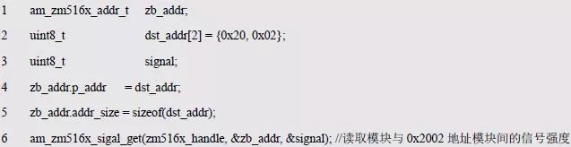
6. Set Destination Address
This function temporarily changes the destination address of the ZM516X module during system operation. The function prototype is:

Where p_zb_addr is a pointer to the address of the target node's Zigbee module, and the type am_zm516x_addr_t is defined as follows (am_zm516x.h):
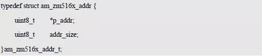
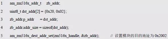
Where p_addr points to the buffer of the network address stored in bytes, and addr_size specifies the length of the address. If the target address is 0x2002, its Zigbee module address can be defined as follows:
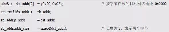
The destination address set by this function is only temporarily valid. After the module restarts, the setting will be lost and the module will reuse the destination address from the permanent parameter configuration. A sample program for setting the module's destination address is shown in Listing 9.42.
Listing 9.42 Setting the Module Destination Address Sample Program
7. Set Header Display
The ZM516X module provides a transparent data transmission channel. If only two modules communicate, there is no need to care which module the received data is sent from. However, if receiving data from multiple modules, the user wants to know the source of the current data. This function can be used to set the source of the received data. The function prototype is:

Where flag is the header display flag. When the value is TRUE, it indicates that when the module receives one frame of data, the first two bytes of the data packet are the network address of the source node. The user can distinguish which module the data is sent from. Conversely, if the value is FALSE, the first two bytes are not added to indicate the network address of the source node. This setting is only temporarily valid and will be lost after the module restarts. The sample program for setting the module header display is shown in Listing 9.43.
Listing 9.43 Setting the Module Header Display Sample Program

8. Go to Sleep
This function puts the ZM516X module into hibernation to reduce power consumption. The function prototype is:

After the module enters sleep, the temporary parameter configuration is not saved, and the module can be woken up by resetting the module function. The sample program that puts the module into hibernation is detailed in Listing 9.44.
Listing 9.44 Bringing the Module into the Sleep Sample Program

9. Set Communication Mode
The ZM516X module supports both unicast (default) and broadcast communication modes. This function can be used to change the communication mode. The function prototype is:
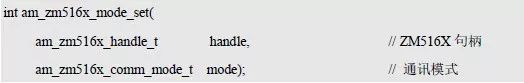
Where mode represents the communication mode, its type am_zm516x_comm_mode_t is an enumerated type, enumerating all possible values, am_zm516x_comm_mode_t is defined as follows:
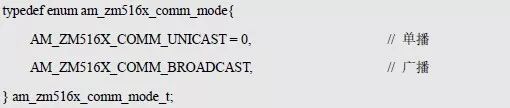
The communication mode set by this function is only temporarily valid and will be lost after the module restarts. The sample program for setting the module communication method is shown in Listing 9.45.
Listing 9.45 Setting the Module Communication Method Sample Program

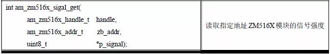
10. Read Signal Strength
This function reads the signal strength between the node of the specified address and the local node, used to evaluate the quality of the link between the two nodes. The function prototype is:
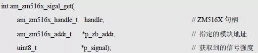
Where *p_zb_addr is a pointer to the address of the target node's Zigbee module, and p_signal is used to get the signal strength. An example program for reading the signal strength of a module is shown in Listing 9.46.
Listing 9.46 Read Module Signal Strength Sample Program
>>> 9.2.5 Zigbee Data Transmission Interface
The data transmission interface realizes transparent data transmission, including both data transmission and reception, with the interface shown in Table 9.9.
Table 9.9 ZM516X Data Transfer Interface Function (am_zm516x.h)

3. Send Data
The ZM516X module provides a transparent channel to the user after the parameters are configured. The user only needs to send data to the serial port of the ZM516X module, and the module will send the data to the configured destination address. AMetal provides a special send data interface function. The user only needs to call the interface to complete the sending of user data. The function prototype is:
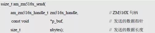
The ZM516X module send function calls the serial port send function with a circular queue. The length of the ring queue is defined in the driver initialization function. The transmitted data pointer is defined as void *, and the user can send any type of data of the specified length.
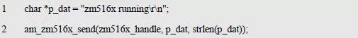
The sample program for sending data is detailed in Listing 9.47.
Listing 9.47 Send Data Sample Program
4. Receive Data
AMetal also provides a special receiving data interface function, the user only needs to call the interface function to complete the reception of user data. The function prototype is:
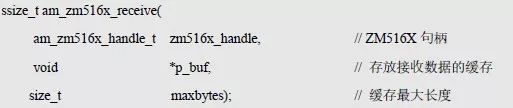
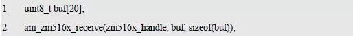
The receiving function calls the serial port receiving function with a circular queue. The user needs to define the length of the circular queue in the driver initialization function according to the needs of the system. The pointer to the receive function's data is defined as void *, which can be used to place the received data in any type of data cache. The sample program for receiving data is detailed in Listing 9.48.
Listing 9.48 Receive Data Sample Program
One of the modules has a local network address of 0x2001, a target network address of 0x2002, another module with a local network address of 0x2002, and a target network address of 0x2001. The two modules send data once every 1s, and then receive the data of the other party. The data is printed out, as detailed in Listing 9.49.
Listing 9.49 Two Modules Send and Receive Data Sample Programs to Each Other

In the program, the data receiving function receiving timeout time of the ZM516X module is 10ms. After snd_tick is added to 100, the data sending function is called once after the time is accumulated to 1s, and the data is sent to the target node.
The above application configures the local network address to 0x2001 and the target network address to 0x2002. The address of the other module is exactly the opposite, so the program of another module needs to modify the program list 9.49 (20 ~ 23) as follows:

>>> 9.2.6 Application Case
AM824ZB is the Zigbee secondary development evaluation board developed by Guangzhou Zhiyuan Electronics Co., Ltd. based on AW824P2EF. The evaluation board integrates a variety of experimental circuits, such as watchdogs, buzzers, digital temperature sensors, thermistors, buttons, etc., to facilitate user interactive experiments using Zigbee for wireless communication.
The AM824ZB development kit includes two AM824ZB development boards, a MiniCK100 emulator, and two antennas for long-distance networking applications. The schematic diagram of the AM824ZB development board is shown in Figure 9.9. The main control core is AW824P2EF. For details, please refer to the website of Guangzhou Zhiyuan Electronics Co., Ltd. ().

Figure 9.9 AM824ZB Development Board Interface Distribution
For complete information, please refer to (Guangzhou Zhiyuan Electronics Co., Ltd.) and (Guangzhou Zhou Ligong Microcontroller Technology Co., Ltd.) website. For samples, please contact the local offices.
Based on the two AM824ZB development boards in the development kit, you can do a simple application: control the flipping of the LED0 status of the other party through independent buttons. Each time the button is pressed, the status of the other LED0 changes (from lit to off). Or from off to light).
1. Application Writing
To implement this application case, as a simple example, we define that when the button is pressed, a string "key_pressed" is sent to the target node, and when the target node receives the "key_pressed" string, it flips LED0.
For the two modules, although the logic of the application is exactly the same, in the networking application, each node must be assigned a different network address, for example, their addresses are set to 0x2001 and 0x2002 respectively. To do this, you need to write a generic function that implements the core application logic. The differences (for example, local address and destination address) are specified by parameters. See Listing 9.50 for details.
Listing 9.50 Example of an Application That Implements LED Control Using Zigbee (app_led_control.c)
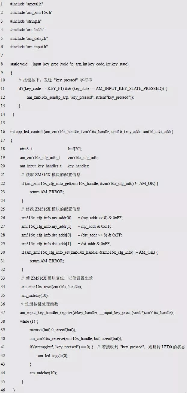
Here, first, according to the parameters, the configuration of the local address and the communication destination address is completed. After the configuration is completed, the setting is made effective by the module reset, and then the key is pressed in the main loop of the while(1), and when the button is pressed, the string "key_pressed" is sent, and then the data is received. If "key_pressed" is received, the state of the local LED0 is toggled.
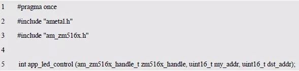
To make it easier for the main program to use, declare its interface to the app_led_control.h file, as shown in Listing 9.51.
Listing 9.51 Application Interface Declaration (app_led_control.h)
2. Main Program Writing
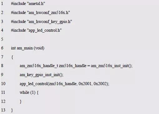
For the sake of distinction, the two boards are called A board and B board respectively. The network address of the A board is 0x2001, and the target address is 0x2002. See Listing 9.52 for details.
Listing 9.52 A Board (Network Address 0x2001) Main Program
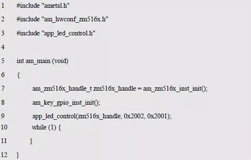
The network address of the B board is 0x2002, and the destination address is 0x2001. See Listing 9.53 for details.
Program Listing 9.53 B Board (Network Address 0x2002) Main Program
High Speed 6PIN Female Connecor for Cable,High Speed GT32 4 PIN Female Connector,High Speed Connetor
Dongguan Zhuoyuexin Automotive Electronics Co.,Ltd , https://www.zyx-fakra.com