Ultrasound systems represent some of the most advanced signal processing technologies currently in widespread use. These systems are designed to meet a wide range of performance, physical, and cost constraints, which leads to numerous trade-offs during their development. To fully grasp the capabilities and limitations of front-end integrated circuits (ICs) such as low-noise amplifiers (LNAs), time gain compensation amplifiers (TGCs), and analog-to-digital converters (ADCs), it's essential to have a solid understanding of system-level design. These components play a critical role in determining the overall performance of the system. Once noise or distortion is introduced at the front end, it becomes nearly impossible to eliminate, making the choice of high-quality front-end ICs crucial for achieving optimal results.
In most ultrasound systems, a multi-sensor array is connected via a long cable—typically around 2 meters—that contains between 48 to 256 micro-coaxial cables. Some systems employ high-voltage multiplexers or demultiplexers to simplify transmit and receive hardware, but this can reduce system flexibility. The most versatile systems are phased array digital beamformer systems, which allow full electronic control over all channels, though they tend to be more expensive due to their complexity. However, modern front-end ICs like the AD8332 dual VGA, AD8335 quad VGA, and AD9229 12-bit ADC are helping to lower costs and power consumption per channel, enabling even budget-friendly systems to achieve full electronic control.
On the transmit side, the beamformer determines the delay pattern to focus the transmitted signal, which is then amplified by a high-voltage driver to excite the transducer. On the receive side, a T/R switch isolates the high-voltage transmit pulses, followed by an LNA and one or more VGAs to amplify the weak received signals. This setup ensures that the system can handle the wide dynamic range required for accurate imaging and Doppler measurements.
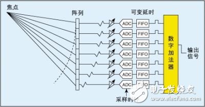
**Figure 1: Basic block diagram of the DBF system**
After amplification, either analog beamforming (ABF) or digital beamforming (DBF) is used to process the signals. Most modern systems use DBF due to its superior handling of large dynamic ranges. The processed receive beam is then used to generate grayscale images, 2D color images, and/or color Doppler outputs.
The primary goals of an ultrasound system are to provide clear internal organ imaging and to assess blood flow using Doppler techniques. To achieve these objectives, the system must address several technical challenges, including signal attenuation, power consumption, and dynamic range. Selecting the right front-end ICs is vital in overcoming these challenges and ensuring reliable, high-quality results.
### 1. Signal Attenuation Problem
Medical ultrasound operates across a frequency range from 1 MHz to 40 MHz. For external imaging, frequencies typically range from 1 MHz to 15 MHz, while venous applications may use up to 40 MHz. As the signal travels through tissue, it experiences attenuation, which increases with both depth and frequency. A typical attenuation rate is about 1 dB/cm/MHz. So, for a 10 MHz signal traveling 5 cm into the body, the round-trip signal loss would be approximately 100 dB.
This significant attenuation poses a major challenge for the receiver. The system must maintain low noise levels while being able to handle very large signals. Additionally, fast overload recovery is essential, as even small leakage from the T/R switch can overwhelm the receiver, causing it to enter a "blind" state until it recovers. This can affect the image quality, especially near the surface of the skin.
### 2. ABF and DBF Systems
In analog ABF and digital DBF ultrasound systems, the signals from each channel are delayed or stored to align the echoes from a specific focal point along the beam. These aligned signals are then summed to enhance spatial resolution. This process provides a theoretical processing gain of 10 log(N), where N is the number of channels.
There are two main approaches to forming images: in ABF, the signals are simulated using analog delays, summed, and then converted to digital values. In DBF, the signals are sampled and stored digitally before being summed. Both methods require precise channel matching and the use of variable gain amplifiers (VGAs). However, ABF systems typically use lower-speed, high-resolution ADCs after summation, while DBF systems require many high-speed, high-resolution ADCs to sample the RF bandpass signal directly.
Fork Type Terminals,Insulated Bullet Sockets Terminals,Insulated Bullet Terminals,Type Fork Insulate Terminal
Taixing Longyi Terminals Co.,Ltd. , https://www.txlyterminals.com