Ultrasound systems are among the most advanced signal processing devices currently in widespread use. As with any complex system, achieving optimal performance involves numerous trade-offs related to performance, physical constraints, and cost. To fully grasp the functionality and performance of front-end integrated circuits (ICs) such as low noise amplifiers (LNAs), time gain compensation amplifiers (TGCs), and analog-to-digital converters (ADCs), it's essential to have a solid understanding of system-level design. These analog components play a crucial role in defining the overall system performance. Once noise or distortion is introduced at the front end, it becomes nearly impossible to eliminate later in the signal chain.
In all ultrasound systems, a multi-sensor array is connected via a long cable—typically around 2 meters—that contains between 48 to 256 micro-coaxial cables. Some systems use high-voltage multiplexers or demultiplexers to simplify transmit and receive hardware, but this often comes at the cost of reduced flexibility. The most flexible systems employ phased array digital beamformers, which allow full electronic control over all channels, though they tend to be more expensive due to the complexity involved. However, modern front-end ICs like the AD8332 dual VGA, AD8335 quad VGA, and AD9229 12-bit ADC are helping to reduce both cost and power consumption per channel, making full electronic control feasible even in lower-cost systems.
On the transmit side, the beamformer sets the delay pattern to focus the transmitted energy, and then a high-voltage amplifier drives the transducer. On the receive side, a T/R switch isolates the high-voltage pulses from the transmitter, followed by an LNA and one or more variable gain amplifiers (VGAs). This setup ensures that weak signals can be amplified without introducing excessive noise.
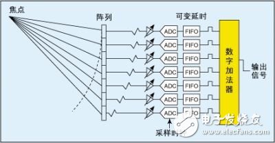
**Figure 1: Basic block diagram of the DBF system**
After amplification, the signal undergoes either analog beamforming (ABF) or digital beamforming (DBF). While continuous wave (CW) Doppler processing is still used, most modern systems rely on DBF due to its ability to handle large dynamic ranges effectively. Finally, the received beam is processed to produce grayscale images, 2D color images, and/or color Doppler outputs.
The primary goals of an ultrasound system are to generate accurate images of internal organs and to detect blood flow using Doppler signal processing. Achieving these objectives presents several technical challenges, including signal attenuation, power consumption, and managing wide dynamic ranges. Selecting the right front-end ICs is critical to overcoming these challenges and ensuring reliable system performance.
**1. Signal Attenuation Problem**
Medical ultrasound operates across a frequency range of 1 MHz to 40 MHz. External imaging typically uses frequencies between 1 MHz and 15 MHz, while venous imaging may go up to 40 MHz. For a given penetration depth, higher frequencies experience greater tissue attenuation. A 10 MHz signal traveling 5 cm into tissue will suffer approximately 100 dB of round-trip attenuation.
This significant signal loss creates a major challenge for receivers, requiring them to have both low noise and high dynamic range. Additionally, the system must quickly recover from overload conditions. Even small leakage through the T/R switch can overwhelm the receiver, causing it to enter a "blind" state until it recovers, which can affect image quality near the surface.
**2. ABF and DBF Systems**
In analog ABF and digital DBF systems, signals from each channel are delayed or stored based on the desired focal point, then summed coherently. This process provides spatial processing gain because the signal is correlated while the noise is not, resulting in a theoretical gain of 10*log(N), where N is the number of channels.
Images can be formed in two ways: either by using analog delays, summing the signals, and converting them to digital after summation (ABF), or by digitizing the signals as close to the transducer as possible, storing them in memory, and then digitally summing them (DBF). Both approaches require excellent channel-to-channel matching. While ABF systems only need a high-resolution, relatively slow ADC, DBF systems demand multiple high-speed, high-resolution ADCs to sample the RF bandpass signal directly.
Conecting Terminals Without Screws
Conecting Terminals Without Screws,Cold Pressing Terminals,Low Pressure Cold Shrinkage Terminal,Cold Shrinkage Cable Terminals
Taixing Longyi Terminals Co.,Ltd. , https://www.txlyterminals.com