I. Project Overview
1.1 Introduction
With the rapid development of the world economy, environmental issues and energy crises have become increasingly prominent. It can be said that environmental issues and energy crises have become one of the greatest threats facing humanity in today's world. Therefore, the exploration and utilization of new energy has become a research hotspot in the world. China has a wealth of new energy for development and use, but the development rate is generally low, but with the development of social economy, new energy is also steadily thinking about the direction of commercial energy.
1.2 Project Background
Solar energy and wind energy are two kinds of renewable energy sources that are widely used at present. They have their own advantages: they are inexhaustible, they can be used without transportation, and they are widely distributed with high reliability. Green energy is good for ecology. But there are also some drawbacks: 1. Low energy density; 2. Poor energy stability. For this reason, a smooth and clean power conversion grid-connected system is particularly important.
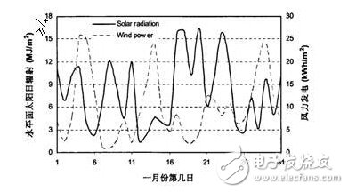
Solar energy and wind energy have strong complementarity in time (as shown on the right). When the sun is strongest during the day, the wind is very small. There is no sunlight in the evening but there is a strong wind. Using the complementarity of these two renewable resources, Make the power generation system the best match in resources. Wind-solar complementary grid-connected power generation systems can play an important role in mitigating grid pressure, power peak shaving, energy saving and emission reduction.
The project aims to enable every household to use new energy, combine solar energy and wind energy, which are complementary energy sources, and convert them into 50Hz alternating current through technical means, so that each household is both a power consumer and It is a power producer. The project has the advantages of green environmental protection and lightening the burden of the power system.
Second, the demand analysis
2.1 Functional requirements
The wind energy and the solar energy are smoothly inverted into alternating current, and the time is automatically selected to be connected to the grid, so that the solar wind power supply and the power grid are connected, and the monitoring thereof is realized (the measurement of the two-way electric quantity);
Monitoring and control of the influence of the load on the power grid when the power is changed;
Undervoltage and overcurrent protection;
Solar panel maximum power point tracking;
Collect the voltage and current values ​​of each part, calculate the efficiency, the harmonic magnitude and the generated power, and display it back to the host computer;
Detecting grid action to prevent the islanding effect from occurring;
Detecting the power quality of the grid and recording the electricity record;
Consider communicating with the host computer to provide users with electricity guidance, such as current electricity price, user power consumption, etc.
2.2 Performance requirements
1. Total harmonic distortion coefficient THD "4%;
2. System efficiency "85%;
Third, the program design
3.1 System function realization principle
1, using SPWM modulation principle
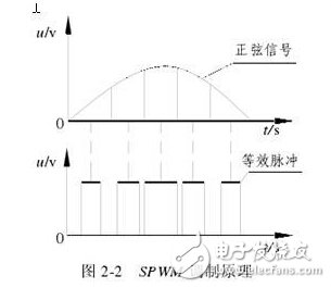
The SPWM modulation principle is shown in Figure 2-2. It can be seen that the equivalent pulse width is sinusoidal. According to the sampling control theory, the higher the pulse frequency, the closer the SPWM waveform is to a sine wave. When the output voltage of the inverter is SPWM waveform, its lower harmonics are well suppressed and eliminated, and the higher harmonics can be easily filtered out, so that a sine wave output voltage with extremely low distortion rate can be obtained.
The SPWM control method is to control the on/off of the switching device of the inverter circuit, so that the output end obtains a series of pulses of equal amplitude and unequal width, and these pulses are used instead of sine waves or other waveforms.
Modulation Principle Theoretically, the width and spacing of the pulse waveform can be accurately calculated after giving the sine half-wave frequency, amplitude, and number of pulses in a half cycle. Then, according to the calculation result, the switching of each switching device in the circuit is controlled, and the required waveform can be obtained. However, in practical applications, the sine wave and the isosceles triangle wave are often used to determine the width of each rectangular pulse. The upper and lower isosceles triangles have a linear relationship with the height and are bilaterally symmetrical. When it intersects any smooth curve, a set of rectangular pulses with equal amplitude and pulse width proportional to the value of the curve function is obtained.
It is called the modulation method. The signal that is desired to be output is a modulated wave, and the triangular wave that receives the modulation is called a carrier. When the modulated signal is a sine wave, what is obtained is the SPWM waveform.
2, DC-AC overall structure and working principle
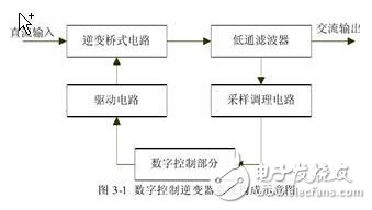
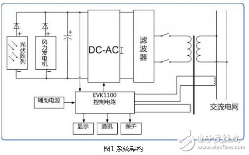
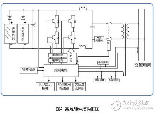
The schematic diagram of the system structure of the digital control inverter is shown in Figure 3-1, including the inverse full-bridge inverter circuit, low-pass filter, drive circuit, digital control part, and sampling and conditioning circuit. The protection function is sampled and executed by the digital control section.
The inverter bridge circuit mainly realizes the conversion of electric energy, converts the direct current voltage into an alternating voltage in the form of a high frequency rectangular pulse, and the low pass filter turns the pulse voltage into a smooth power frequency alternating current. The sampling conditioning circuit is used to sample the output state variables and adjust the variables to a digital control platform to accept signals within the allowable range. The digital control part is the main processing and processing link. The appropriate algorithm and measures are used to make the output meet the requirements of the system design. The drive circuit is the execution link.
3. MPPT control method
The voltage detection module in Figure 2 is used to implement the maximum power point tracking (MPPT) function. The AD sampling input voltage Ud of the controller is compared with the maximum power point (assumed to be 30V) and adjusted by the PI algorithm. When Ud is greater than 30V, the amplitude of the SPWM modulation signal is reduced, and when the Ud is less than 30V, the amplitude of the SPWM modulation signal is increased, thereby achieving the maximum power point tracking function.
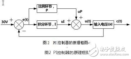
The block diagram of the PI controller is shown in Figure 2. The PI control algorithm uses an incremental PI control algorithm. Its target input is the AD input when the amplitude of the input voltage Ud is 30V. The actual input is the AD input of the input voltage Ud, and the subtraction between them is deviated. The signal e(t) is then used to obtain the deviation of the control quantity by the PI formula. Finally, the control quantity is converted into the control data of the SPWM, so that the whole system becomes a closed-loop system, and the control of the SPWM is realized.
4. Control method of the same frequency in phase
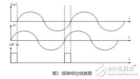
The phase detector module can realize the control of the same frequency in phase. The control method of the same frequency in phase is shown in Fig. 3. The phase detector reflects the frequency and phase information of the feedback signal uf and the reference signal Uref through a rectangular circuit in the form of a rectangular pulse, and then sends it to the capture unit module or the controller of the controller. The port counts the rising edge and the falling edge, and the rising edge to the rising edge. The time difference between the rising edge and the falling edge is the phase difference between uf and Uref. The time from the rising edge to the rising edge is the frequency information of uf, and then passes. The software continuously changes the SPWM step size and the value of the accumulator to achieve frequency tracking. The phase tracking is realized by continuously correcting the SPWM output start address.
3.2 Hardware platform selection and resource configuration
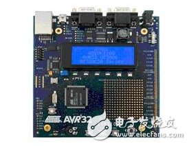
This system is developed using the EVK1100 development board.
The EVK1100 is an evaluation kit and development system based on the AVR32 AT32UC3A microcontroller controller. It comes with a rich set of peripherals, memory, and the full potential of the AVR32 device.
Support AT32UC3A
Ethernet port
Sensor: light, temperature, potentiometer
4x20 blue LCD (PWM inverter backlight)
JTAG connector, Nexus, USART, USB 2.0 interface, TWI interface, SPI.
1, DC-AC inverter circuit
The DC-AC inverter circuit performs the function of amplifying the power of the SPWM signal and requires high amplification efficiency. This system selects IR2010 floating gate driver to drive H bridge. The driving chip withstand voltage is up to 200V, output current is 3.0A, output voltage is 10-20V, and the typical time of turn-on and turn-off is 95ns and 65ns respectively. The power tube is made of high-efficiency MOS tube IRFB23N15D with high withstand voltage, small on-resistance and small switching loss. High efficiency drive circuits and MOS tubes ensure overall system efficiency.
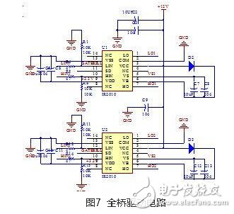
As shown in Figure 7, a two-bridge driver IR2010 is used to form a full-bridge driver circuit. IR2010 uses a 3.3V logic power supply and a 12V low-side drive channel power supply to directly add a pair of complementary symmetrical SPWM signals generated by the processor to the logic signal input of IR2010. The SPWM signal of the IR2010 drive channel output is input logic. In phase, the switching control of the H-bridge can be achieved. The IR2010's shutdown control terminal (SD) can receive the overcurrent protection circuit's shutdown signal for overcurrent protection.
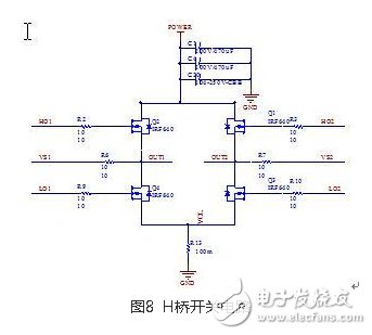
The H-bridge power conversion circuit is shown in Figure 8. It consists of four MOS power transistors (IRFB23N15D) Q1~Q4. Each MOS transistor forms one bridge arm of the H-bridge. OUT1 and OUT2 can be connected to external loads. The complementary symmetrical SPWM signal generated by the controller realizes the switching control of the H bridge through the full bridge driving circuit: when Q2 and Q3 are simultaneously turned on, and Q1 and Q4 are simultaneously turned off, the output current direction is from OUT1 to OUT2; when Q1, Q4 At the same time, when Q2 and Q3 are turned off at the same time, the output current direction is from OUT2 to OUT1, thereby realizing DC-AC inverter.
2, overcurrent detection circuit
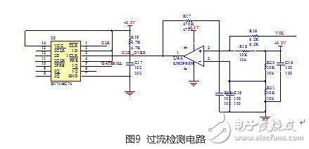
As shown in Figure 9, the VOL pin inputs the voltage from the low-side sampling resistor of the H-bridge. The resistors R16, R18, R20, and R21 determine the preset threshold voltage. When the sampling voltage is higher than the threshold, the comparator LM2903 outputs a rising edge. The 1D terminal of the flip-flop 74HC74 is latched high to the 1Q terminal, and the 1Q terminal is connected to the SD terminal of the IR2010, thereby turning off the entire H-bridge output for overcurrent protection. The 1Q terminal is simultaneously connected to the GPIO of the AT32UC3A, and the overcurrent signal is detected by software. Once the overcurrent can be cleared, the 1Q is cleared by the CLR signal to realize automatic recovery of the overcurrent.
3, input voltage detection circuit
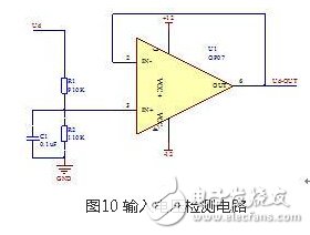
As shown in Figure 10, the input voltage Ud is divided by a resistor to a reasonable output range, and is connected to the op amp in the form of a voltage follower to reduce the output impedance. The output signal Ud-OUT can be directly connected to the ADC input on the AT32UC3A. On the pin.
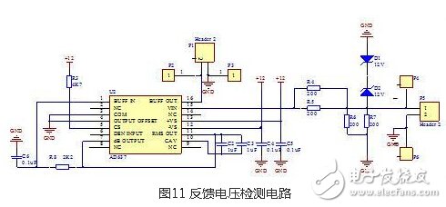
4, feedback voltage detection circuit
As shown in FIG. 11, the effective value measurement chip AD637 is used to organize the effective value of the feedback signal Uf into a DC component to be input to the AD input of the AT32UC3A, so that the corresponding amplitude adjustment can be performed in the software.
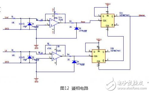
5, phase detector circuit
The phase-detecting circuit is as shown in FIG. 12, and the feedback voltage Uf and the sinusoidal reference voltage Uref are shaped into rectangular waves by the Zener diode and the operational amplifier, and the AT32UC3A counts according to the rectangular wave level, and the count value reflects the frequency information, so according to the count value Frequency tracking can be achieved by changing the SPWM step size. The phase information can be obtained by the time difference of two rectangular waves. The two rectangular waves are used as the clock signal of the edge trigger, so that the time difference of the rectangular wave is reflected by the high-level pulse width of the output phase_out of the flip-flop, and the phase_out is connected to the AT32UC3A. On the upper IO, the controller corrects the SPWM output start address according to the pulse width signal to implement phase tracking.
3.3 system software architecture
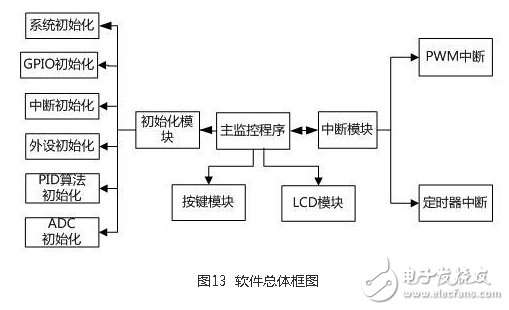
Software structure diagram
The system software design adopts a modular design method, and the sub-programs that complete the specific functions are combined into functional modules, which are uniformly called by the main monitoring program. The software structure diagram is shown in Figure 13. The main functional modules included in the system software are: initialization module, interrupt module, button module and LCD module.
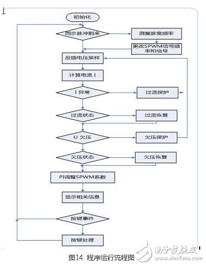
3.4 System Software Process
3.4 System Expected Results
Physical prototype: EVK1100 based wind-solar complementary grid-connected power generation system, including inverter, energy harvesting part, user interface part.
Car Accessories is a new field of our company develop, which including the USB Charger Socket, LED Light , Car Lighter Plug and etc.
The USB Car Charger is available in many different modal, there is round and rectangle shape. The bottom of this USB Charger could be solder terminal also could be wiring. All the input and output are direct current and it is normally applied in the Marine, Truck, Camper, motor home, boat etc.

The LED Light is IP56 waterproof rating, which could better protect the LED Bulb from the water or harsh environment. Energy Saving
LED Lamp could not only used in RV but also could use in many other application of Marine, Truck, Camper, motor home, Limousine, Travel trailer, caravan, boat etc. There are 12V DC 24VDC Voltage could be choose from. The Emitting Color could choose, including Red, White, Blue and etc. The Working life of the Ceiling Light is 30,000 Hours, which is a long time for use.

Cigarette Lighter Plug is also available in many modals, the input and output are direct current and it is normally applied in the Marine, Truck, Camper, motor home, boat etc.Normally fits 18AWG wire cable

Car Accessories
Car Accessories,Auto Accessories,Car Parts,Auto Parts
YESWITCH ELECTRONICS CO., LTD. , https://www.yeswitches.com