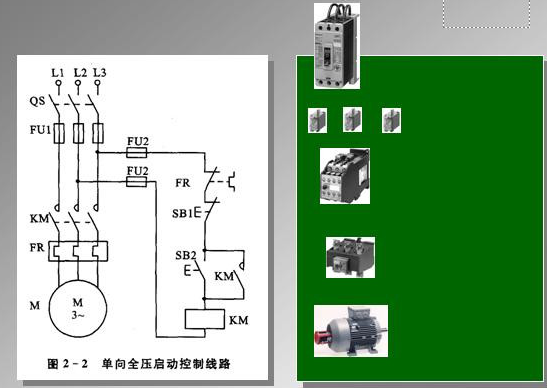
In order to express the design intent of the structure and principle of the production machinery and electrical control system, to facilitate the installation, commissioning, use and maintenance of the electrical system, the electrical components and their connection lines in the electrical control system are expressed in a certain pattern. This is the electrical control. System diagram. A circuit that connects wires, such as motors, electrical appliances, and meters, according to certain requirements, and implements certain control requirements.
The electrical schematic to be discussed here is one of the electrical system diagrams. It is drawn according to the working principle of the control line diagram, and has a simple structure and a clear hierarchy. The electrical system diagram mainly includes electrical schematic diagram, electrical layout diagram, electrical installation wiring diagram, etc. The drawing software includes electrical CAD, protell99, Cadence and so on.
The role of the electrical schematic:
The electrical schematic diagram generally consists of main circuit, control circuit, protection, power distribution circuit and so on. Mainly used to study and analyze the working principle of the circuit.
The electrical schematic diagram is a representation of the relationship between the electrical working principle of the equipment and the functions of the various electrical components. The use of electrical schematics and techniques is very useful for analyzing electrical circuits and troubleshooting machine circuit faults.
It should be noted that the function of the electrical schematic diagram is to facilitate the reading and analysis of the control circuit. It should be drawn in the form of electrical components according to the principle of simple structure and clear hierarchy. It includes the conductive parts and terminals of all electrical components, but does not draw according to the actual arrangement position of the electrical components, nor does it reflect the actual size of the electrical components.

The main types of electrical schematics:
Electrical circuit diagrams have schematics, block diagrams, component assembly, and symbologlot diagrams.
Schematic
The electrical schematic diagram is used to indicate the working principle of the equipment and the role between the electrical components. It is generally composed of the main circuit, the control execution circuit, the detection and protection circuit, and the power distribution circuit. This kind of diagram, because it directly reflects the electronic circuit and electrical structure and their logical relationship with each other, is generally used in the design and analysis of circuits. When analyzing the circuit, you can understand the actual working condition of the circuit by identifying the various circuit component symbols drawn on the drawing and the connection between them.
The electrical schematic diagram can be divided into the whole machine schematic diagram, the unit part circuit schematic diagram, and the whole machine schematic diagram refers to the partial circuit diagram of all the circuits assembled together.
Block diagram (block diagram)
A block diagram is a circuit diagram that uses blocks and wires to represent an overview of the circuit's operation and configuration. To some extent, it is also a schematic, but in this drawing, there are almost no symbols other than boxes and connections. The main difference between it and the above schematic is that the whole components of the circuit and their connection methods are specifically drawn on the schematic diagram, and the block diagram simply divides the circuit into several parts according to functions, and each part is depicted. In a box, add a simple text description to the box, and use a line (sometimes with a line connecting arrows) between the boxes to illustrate the relationship between the boxes. Therefore, the block diagram can only be used to reflect the general working principle of the circuit, and the schematic diagram can be used as the basis for collecting components and making circuits, in addition to specifically indicating the working principle of the circuit.
Component assembly and symbol mark diagram
It is a type of drawing used for circuit assembly. The symbols on the figure are often the shape of the physical components of the circuit components. This circuit diagram is generally used for both principle and physical comparison. The printed circuit board is covered with a layer of metal foil on an insulating board, and then the metal foil which is not needed for the circuit is etched away. The remaining part of the metal foil serves as a connection line between the circuit components, and then the element in the circuit The device is mounted on the insulating board, and the remaining conductive metal foil on the board is used as a conductive connection between the components to complete the circuit connection. Component assembly drawings and schematics are quite different. It mainly considers whether the distribution and connection of all components are reasonable. Considering factors such as component volume, heat dissipation, anti-interference, anti-coupling, etc., the printed circuit board designed by combining these factors is difficult to be completely consistent with the schematic diagram from the outside.
Electric Hot Plate,Hot Plate,Double Burner Hot Plate,Single Burner Hot Plate
xunda science&technology group co.ltd , https://www.gasstove.be