The vehicle instrument is one of the most important human-computer interaction devices on the vehicle, and is mainly used to provide the driver with information about the running state of the vehicle. With the wide application of electronic technology, traditional automotive instruments will gradually be replaced by microprocessor-based electronically controlled digital meters.
1 System working principle and functional block diagramIn this paper, the ADμC845 microcontroller and related sensor devices are used to design the digital instrument system for vehicles.
The system function is coordinated by hardware and software. The hardware part mainly completes the collection and conversion of various sensor signals and the display of various data information; the software mainly completes the signal processing and control functions. System function block diagram shown in Figure 1. The ADμC845 microcontroller acquires the output signal of each sensor and converts it by its own analog-to-digital converter. The converted data is output by the LCD screen and LED indicator, when part of the data reaches or exceeds the set peak value. Output an alarm signal.
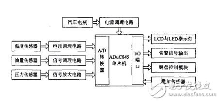
Figure 1 system functional block diagram
2 hardware design2.1 main control module
This system uses ADμC845 as the main chip. It is a new high performance 24-bit data acquisition and processing system from Analog Devices. It integrates two high-resolution delta-sigma ADCs, a 10/8-channel input multiplexer, an 8-bit MCU and program, and a data flash/electrical erase memory. A 62KB flash/electric erase program memory, a 4KB flash/electric erase data memory and a 2304B data RAM are also available.
The ADμC845 can generate a 12.58MHz high frequency clock through an on-chip latching loop PLL to operate on a 32KHz external crystal. The clock can be sent through a programmable clock that is separated from the MCU core clock operating frequency. The on-chip microcontroller is an optimized single instruction cycle 8052 flash MCU. The MCU is kept compatible with the 8051 command system. Has a performance of 12.58 MIPS. The two unique ADCs (primary and auxiliary) consist of an input multiplexer, a temperature sensor and a programmable gain amplifier PGA that directly measures the low amplitude signal. Both the primary and secondary ADCs use high frequency "chopping" techniques to provide excellent DC (DC) offset and offset drift specifications. The ADμC845 has both serial download and scheduling modes. Pin competing mode is available through the EA pin.
The analog-to-digital conversion part of the system uses the 24-bit depleted-Δ ADC of the MCU itself. It can be set to 4/5 fully differential input channels or 8/10 pseudo differential input channels. The main channel has a buffer and internal buffer disable function. The input range is divided into 8 blocks from ±20mV to ±2.56mV. You can select one gear when using. These channels are used to directly convert the signal from the sensor. The auxiliary channel is used to receive the input of the auxiliary signal. This channel has no buffer and only one input range is fixed at ±2.56V.
2.2 sensor module
2.2.1 Temperature sensor. The temperature sensor of this system is a precision grade platinum resistance temperature sensor PTl000. It has good linearity, small dispersion of temperature coefficient and stable performance. This sensor is installed in the coolant circuit to measure the temperature of the coolant. The temperature range is -40~+130°C. The output voltage of PTl000 is directly connected to the analog channel of analog-to-digital conversion of the single-chip microcomputer through the voltage conditioning circuit. When the coolant temperature is too high. Output an alarm signal.
2.2.2 Hall sensor. The speed sensor and the engine speed sensor use a Hall sensor. When the wheel starts to rotate, the Hall sensor starts to generate a series of pulse signals. By calculating the instantaneous speed and engine speed of the vehicle by counting it in unit time, the accumulated pulse signal can calculate the mileage traveled by the vehicle. Since the duty cycle of the pulse position remains constant at any speed, in order to improve the waveform, the pulse signal is shaped and amplified by the RC filter and the three-stage tube amplification processing method.
2.2.3 Oil quantity sensor. The oil quantity signal is an analog signal, so we obtain the pulse signal through the high-precision capacitive oil é¼ sensor, and after filtering, amplifying and linearizing the circuit, we send the analog channel of the single-chip analog-to-digital conversion. Due to the bumps in the running of the vehicle, the liquid level of the fuel in the mailbox is constantly oscillating, so the component parameters in the conditioning circuit are particularly important. A reasonable circuit will help with data processing in the software. The time to go one week - from which the running speed is calculated.
2.2.4 oil pressure sensor. The pressure sensor uses an electronic oil pressure sensor that is mounted on the main oil gallery of the engine. The pressure range is 0.01~0.6Mpa. When the engine is running. The pressure measuring device detects the pressure of the oil and converts the pressure signal into an electrical signal. After voltage amplification and current amplification, the amplified electrical signal is sent to the analog channel of the single-chip analog-to-digital conversion through the signal line. The MCU compares the converted value with a preset alarm voltage value. When lower than the alarm voltage. Output an alarm signal.
2.3 display module
The display module includes an LED indicator and an LCD liquid crystal display. The LCD uses a graphic dot matrix liquid display LSDl2864CT with 20 external pins. It uses an 8-bit data bus and five control lines to connect to the microcontroller. as shown in picture 2. Graphics and 8x4 (16x16 dot matrix) Chinese characters can be displayed. A liquid crystal display with a Chinese character library is used. Make the displayed data more intuitive and clear. The contents of the LED display include low oil pressure, too high cooling water temperature, too little fuel, no loose brakes, no closed doors, and the trunk is not closed. Please fasten the seat belts. The contents of the LCD liquid crystal display include vehicle speed, mileage, engine speed, coolant temperature, fuel quantity, oil pressure, and the like.
2.4 keyboard control circuit
The keyboard control circuit is composed of P3.0 to P3.5 of the ADμC845. The connection is shown in Figure 2. The keyboard has 2 rows and 4 columns with a total of 8 keys. Use 6 I/0s as control lines. P3.0 and P3.1 are used as the line scan lines, and P3.2 is used. P3.5 acts as a column reply line to form a matrix keyboard. In operation. To prevent keystrokes and jitter, when a key is pressed. The program does not immediately enter the button handler. The program is processed only when the button is pressed and released.
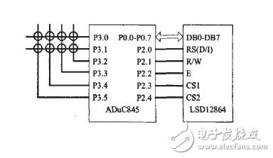
Figure 2 shows the keyboard circuit
3 software designThe software design of the system includes the system main program, keyboard scanning subroutine, interrupt subroutine, data acquisition and A/D conversion subroutine, LCD and LED indicator subroutine, alarm signal subroutine, watchdog timer and Power monitor subroutine, etc.
3.1 main program design
The main program mainly implements initialization of the system and calls to each subroutine, as shown in Figure 3. System initialization mainly includes initialization of liquid crystal display, display buffer value, interrupt and register flag value.
3.2 data acquisition and conversion subroutine design
This subroutine samples, quantizes and performs corresponding arithmetic processing according to the corresponding analog signal input from the analog channel, and finally returns the value of the corresponding signal to the main program.
3.3 interrupt subroutine
The interrupt sources of this system mainly include interrupt pulses generated by Hall sensors, watchdog timers and power monitors. The ADμC845's interrupt system can provide 11 interrupt sources, which can fully meet the requirements of this system. The Hall element outputs a low level every revolution, and the number of accumulated levels combined with the circumference of the tire can be used to derive the mileage of the vehicle. The frequency divider is used to obtain a low level from the Hall element, and the low level generates an interrupt and starts the counter. When the second low level comes, the counting is stopped, and the time of one revolution is obtained, thereby calculating the running speed. The number of times the Hall level changes in the unit time. The real-time speed of the engine can be derived.
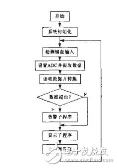
Figure 3 main program flow chart
3.4 Display and alarm subroutine
The display subroutine extracts the display buffer value according to the keyboard scan result, and then completes the display output of the value and the symbol on the LCD screen and the LED light.
When abnormal conditions such as excessive coolant temperature, insufficient oil setting, or insufficient oil pressure occur. The alarm subroutine illuminates the corresponding indicator and causes the audio device to generate an alarm signal of a different frequency to draw the user's attention.
4 anti-jamming designThe ADμC845 microcontroller has excellent anti-electromagnetic interference performance. But to ensure a stable and reliable operation of the system. This design still uses anti-jamming measures combined with hardware circuit design and software watchdog program design.
The hardware circuit design mainly includes the following parts: the system power is obtained by the car battery power supply after being transformed, stabilized, and filtered. And add a current limiting resistor and a Zener to prevent high voltage and inverting input: in order to save mileage data in time when power is lost. Add a 1000F electrolytic capacitor at the input end of the power supply: use a one-point connection to reduce the interference between the digital and analog circuit power supply, especially the interference of the digital circuit to the analog circuit; use the optical isolator, the microcontroller system and various sensors The switch is electrically isolated.
Software anti-jamming refers to software programming of the ADμC845's Watchdog Timer (WDT) and Power Monitor (PSMI). After enabling the watchdog. If the "feed dog" operation is not performed within the predetermined time, that is, the WDE bit in WDCON is set to 1, the watchdog will reset the system service or generate an interrupt; when the digital power or analog power supply drops to a certain value, a PSMI interrupt is generated. The low level of CMPA and CMPD indicates whether the digital power supply or the analog power supply is low. If CMPA and CMPD return to high level. Clear PSMI after holding high for 250ms.
5 ConclusionThe innovation of this paper is to design the digital instrument system for vehicles with the new ADμC845 single-chip microcomputer and sensor with outstanding anti-interference performance and liquid crystal display. The widescreen LCD display makes the display function of this system even more powerful. At the same time, the new ADμC845 microcontroller. It is also the next step to develop an integrated information system based on this, expand the display and control information types, and expand a broader space.
Dog Training Receiver,Waterproof Dog Shock Collar,Rechargeable Remote Dog Trainer,Small Dog Shock Collar With Remote
Elite-tek Electronics Ltd , https://www.aetertek.ca