Abstract: In order to make wireless power transmission no longer need power lines and huge charging devices when charging multiple devices, for example, experimental mobile devices (such as mobile phones) can be charged near wireless transmission devices, and can be changed by changing mobile phones and other devices. The location, angle, distance from the transmitting device, etc. enable wireless charging. In order to solve the long-term compatibility problem, it is proposed to use capacitive power transfer (CPT) to apply AD-DC and DC-AC conversion technology to charge mobile devices. By improving the design, whether it is a rectifier bridge or a bias network, we use switching power supplies to improve efficiency. This solution is more suitable for integrated circuit (IC) implementation than conventional architectures. Experimental applications show that the system can improve wireless power transmission efficiency by 90%.
Keywords: wireless transmission; magnetic coupling; power transmitter; AC/DC
Due to the convenience of customers' charging needs, many companies joined the Wireless Power Consoration (WPC), which was established in 2008, and established a universal wireless transmission standard (QI). This standard enables portable devices of different models, different countries and different power requirements to share one power supply. Multiple devices no longer need power lines and huge charging devices when charging, which solves the long-term compatibility problem. However, the power transmission efficiency under the WPC standard is not high, and the research goal is to reduce the wireless transmission loss of electric energy, and realize charging for a low-power portable mobile device battery.
1 Wireless transmission through electromagnetic coupling and its advantagesAlthough acoustic coupling and optical coupling are also evolving, electromagnetic coupling is the most efficient. Traditional inductive transmission techniques (IPT) have significant limitations. Because it can not pass through the metal barrier, the transmission efficiency is low, and it is susceptible to electromagnetic interference and the like. The wireless power transmission based on magnetic field resonance coupling establishes a transmission channel between the transmitting and receiving devices through resonance, which can realize long-distance energy transmission between channels, and optimizes the power conversion circuit and reactive power compensation to maximize the possibility. Improve energy transfer efficiency to efficiently transfer energy. The effect of the inductance solenoid coil diameter and the working time of the switching circuit of the transmission device on the transmission power is studied experimentally. Our team plans to use capacitive power transfer (CPT) to apply AC-DC and DC-AC conversion technology to charge mobile devices.
Wireless Capacitive Power Transfer (CPT) technology has recently been proposed as a backup contact power transfer solution, and the CPT interface is constructed in a pair of coupled capacitors. The rest of the power conversion system, including the inverter and rectifier structure, remains the same. Due to the characteristics of magnetic induction, power consumption can be reduced, and at certain power levels, components can be used to minimize the capacitance structure. So the most significant advantage of CPT is its low power loss, cost and size. However, this is not a preferred solution in high power applications. For this reason, most existing CPT solutions are focused on low-power applications and portable electronic devices, such as wireless toothbrush chargers, or wireless handset chargers at the point of the power transfer interface and capacitively coupled matrix.
For inductive transmission technology, CPT has the following characteristics:
1) CPT is based on electric field coupling, so it is necessary to provide a high frequency AC voltage on the coupling plate.
2) A complete CPT system contains at least two pairs of coupling plates to provide complete circulating current between the power supply and the receiver.
3) When there is a metal barrier between the coupling plates, this coupling can be thought of as a series connection of two capacitors, which means that the CPT can transfer energy through the metal barrier.
4) Compared to IPT, the CPT system can be greatly reduced because electromagnetic field interference is enclosed in the volume of the connecting plate.
5) The removal of heavy and expensive magnetic materials and coils, the size of the circuit can be reduced. The structure of the wireless battery charger is shown in Figure 1.
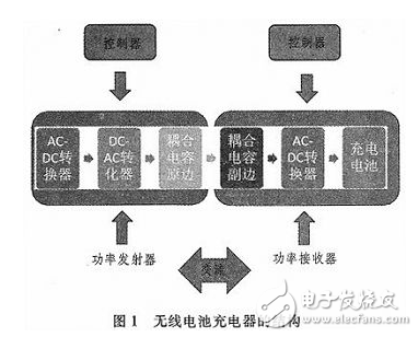
The power transmitter is connected to the power grid and the power receiver is integrated on the mobile device. Power issuance and power acceptance are magnetically coupled. After AC-DC and DC-AC conversion, the power is output on the basis of a reasonable control of the resonance box, and then AC-DC is converted into a DC voltage to charge the battery. Coupling resonant wireless power supply technology This new power supply method can not only increase the distance of wireless power supply to the meter level, but also break the bottleneck of wireless energy transmission distance, and also separate the physical connection between the power supply equipment and the power supply equipment. In this way, the safety and safety of the electrical equipment can be improved while improving the safety and usability of the electrical equipment.
Wireless Capacitive Power Transfer (CPT) technology has recently been proposed as a backup contact power transfer solution, the CPT interface is a pair of coupled construction capacitors. The rest of the power conversion system, including the inverter and rectifier structure, remains the same. Since the magnetics reduce power consumption as needed and without shrinking, at some power levels, the cost and size of the electrically isolated components can interface with the minimized capacitance. So the most significant CPT advantage is its cost and size at low power levels. However, this is not a preferred solution in high power applications. For this reason, most existing CPT solutions are focused on low-power applications and portable electronic devices, such as wireless toothbrush chargers, or wireless handset chargers that implement a matrix of power-transfer interfaces and capacitive coupling. . Printing and MEMS technology in the application CPT demonstrates the promise of advancement in these acceptance technologies in consumer electronics applications.
2 Using switching power supplies to increase power efficiencyIn previous constructions, power efficiency was regulated by a resistance adjustment system that introduced a severely reduced efficiency parallel to the bridge rectifier resistive load. The AC-DC rectifier is implemented by a full-wave rectifier. In such circuits, power efficiency is largely affected by both conduction and switching losses. In addition, power efficiency is affected by power loss in the bias circuit. The most important thing is to bring more convenient power supply for special occasions, such as underwater inspection, oilfield mine, mountain desert, chemical industry, etc. Therefore, the magnetic coupling resonant wireless power supply technology has good application value and research significance.
Improved design, both for rectifier bridges and bias networks, we use switching power supplies to increase efficiency. This solution is more suitable for integrated circuit (IC) implementation than conventional architectures. In addition, the MOSFET on the receiver frame has a very low on-resistance, so the power loss is severely reduced compared to conventional systems using diodes and resistors.
A Brushless DC Electric Motor (BLDC motor or BL motor), also known as electronically commutated motor (ECM or EC motor) and synchronous DC motors, are synchronous motors powered by direct current (DC) electricity via an inverter or switching power supply which produces an alternating current (AC) electric current to drive each phase of the motor via a closed loop controller. The controller provides pulses of current to the motor windings that control the speed and torque of the motor.
The construction of a Brushless Motor system is typically similar to a permanent magnet synchronous motor (PMSM), but can also be a switched reluctance motor, or an induction (asynchronous) motor.
The advantages of a brushless motor over brushed motors are high power-to-weight ratio, high speed, electronic control, and low maintenance. Brushless motors find applications in such places as computer peripherals (disk drives, printers), hand-held power tools, and vehicles ranging from model aircraft to automobiles.
24v brushless motor,24v brushless dc motor,24 volt brushless motor,Brushless dc motor 24v 500w
Shenzhen Maintex Intelligent Control Co., Ltd. , https://www.maintexmotor.com