In the design of RF amplifying circuit, the problem of input and output impedance matching is generally involved, and the design of the matching network is the key to solve the problem. If you know the impedance required by the network design, you can use the RF circuit design software (such as RFSim99) automatically designs a matching network, which is very convenient. Generally, when the impedance matching requirements are not very strict, or only concerned with other indicators, the input and output impedance of the device can be approximated (sometimes the dispersion of device parameters is also required), as long as the design error is small. . However, in the design of RF power amplifiers, the design of the driver stage and the final stage power output must increase the power gain and high efficiency. It is important to know the input and output impedances of the driver stage and the power output stage. Input and output impedances at typical frequencies and powers are generally given in the device manual for power transistors, providing a reference for engineers, but due to the dispersion and operating conditions of the power tube parameters (such as operating frequency, temperature, bias) When the power supply voltage, input power, output power, etc. change, the parameters in the manual are greatly different from the actual conditions. Sometimes in order to reduce the power consumption of the product, it is necessary to design a well-matched and high-efficiency RF power amplifier. It is necessary to measure the input and output impedance of the power tube under certain operating conditions. In the process of measurement, the preferred instrument is an expensive network analyzer, but without a network analyzer, you can seek to use ordinary instruments (such as oscilloscopes, impedance testers, etc.) for measurement. The following describes a method for measuring the input and output impedance of an RF power tube under actual operating conditions using a common measuring instrument.
2 General method of impedance measurementImpedance measurement methods mainly include three methods: bridge method, resonance method and voltammetry. The bridge method has high measurement accuracy and is a commonly used high-precision measurement method, but measures the impedance of an active nonlinear large-signal working device such as an RF power tube, in particular, requires the power tube to be measured under actual working conditions. Certain difficulties, the bridge method is difficult to apply. The resonance method is also difficult to apply when the RF power tube is required under actual workpiece conditions. The main reason is that the waveform under the nonlinear large signal is not a sine wave. Voltammetry is the most classical method of impedance measurement. The measurement principle is based on Ohm's law, that is, the impedance ZX can be expressed as ZX=UXejθ/IX, UX is the effective value of the voltage drop across the impedance ZX, and IX is the current flowing through the impedance ZX. The effective value, θ is the phase difference between voltage and current. However, the voltage and current of the base and collector of the RF power tube are not sinusoidal, so the fundamental IX and θ are difficult to accurately measure. Obviously, the voltammetry has great limitations here. These three methods are difficult to apply in measuring the input and output impedance of the RF power tube under actual working conditions. The following describes a method for indirectly measuring impedance. It also solves the problem of filtering harmonics and requiring the power tube to be tested under actual working conditions. The problem has proved that this method is simple and easy.
3 Method of indirect measurement of impedance by transfer function method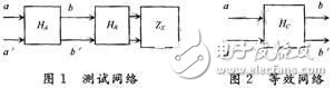
In Figure 1, the networks HA, HB, and ZX form a test network, and the HC in Figure 2 is its equivalent network. HA and HB are passive linear two-port networks that play the role of matching, isolation and filtering, so that a better sine wave can be observed at bb'. The transfer function of HC can be expressed as:
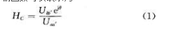
Where Uaa', Ubb' is the effective value of the voltage at aa' and bb', and θ is the phase difference of the voltage at aa' and bb'. As long as Uaa', Ubb' and θ are measured, the transfer function HC can be obtained. Since HA and HB are known linear networks, the impedance ZX to be measured can be obtained by calculation.
4 Test network design principlesFirst of all, the design of HA and HB networks should be as simple as possible according to actual needs. If the network is more complicated, not only the amount of calculation is increased, but also the error of calculating the impedance is increased.
Secondly, the selection of HA and HB network components should try to select the resistors, capacitors and inductors close to the ideal component model, and use the inductor components as little as possible, because the Q value of the inductor components cannot be made very large, and the actual model of the inductor components is complicated. When the actual model is used, the circuit model is complicated, which increases the amount of calculation and increases the error. Before using the component, the component parameter value must be accurately measured with a precision impedance meter, and the influence of the distribution parameter should be minimized when the circuit is overlapped.
Again, the power tube must be in normal operation during the test, and the network is in a resonant state or slightly deviated from the resonance state (the Q value of the resonant tank is not large). The parameters thus measured have practical significance at a specific operating frequency and operating state.
Finally, the probe capacitance at bb' should be as small as possible, and the input resistance of the probe should be as high as possible. Only the capacitance of the probe must be considered in the calculation. The size of the probe must be measured before testing.
5 RF power tube input and output impedance measurement examplesThe RF power tube application manual generally has input and output impedances of the power tube under certain operating conditions. When designing the RF power amplifier, if the power tube works in the typical working state of the manual, you can directly use the power tube input and output impedance parameters provided in the manual. Although the parameters of the power tube have a certain dispersion, the error is not Big. If the operating conditions of the RF power tube change (especially the operating frequency), the parameters in the manual are inaccurate and can only serve as a reference. For example, the input and output impedance data of the VSC band RF power tube 2SC2630 produced by Mitsubishi Corporation of Japan is: Zin=0.8+j1.2 Ω, Zout=1.5-j0.6 Ω, @Po=60 W, VCC=12.5 V, f = 175 MHz. For example, the input and output impedance data of the RF power tube 2SC1971 operating in the VHF band is: Zin=0.8+j3.2 Ω, Zout=6.2-j3 Ω, @Po=6 W, VCC=13.5 V, f=175 MHz .
The Ideal RJ45 Cat6 Modular Plugs (25-Pack) support speeds associated with Category 6-cable. These plugs offer gold contacts and are suitable for solid or stranded 22 - 23 AWG conductors. Refer to the instructions sheet for terminating the plugs.
- Designed for use with Cat6 universal twisted pair wire
- 50-micron gold contacts
- Suitable for solid or stranded 22 - 23 AWG conductors
- 3-piece, 8-position/8-contact design provides easy installation and optimal performance
- Crimps with a standard RJ-45 crimp die
CAT6 Modular Plug, modular cat 6, 8P8C STP Modular Plug, RJ45 Modular Plug
NINGBO UONICORE ELECTRONICS CO., LTD , https://www.uniconmelectronics.com