Circuit noise
For the noise nominal in the electronic circuit, it can be broadly considered that it is a general term for all signals other than the destination signal. At first, the electronic signals that caused the noise emitted by audio equipment such as radios were called noise. However, the consequences of some non-purpose electronic signals on electronic circuits are not all related to sound. Therefore, people gradually expanded the concept of noise. For example, those electronic signals that cause white lines on the screen are also referred to as noise. It may be said that all signals except the intended signal in the circuit, regardless of whether it affects the circuit, can be called noise. For example, ripple or self-oscillation in the power supply voltage can adversely affect the circuit, causing the audible device to emit hum or cause the circuit to malfunction, but sometimes it may not cause the above consequences. For such ripple or oscillation, it should be called a kind of noise of the circuit. There is also a radio wave signal of a certain frequency, which is a normal destination signal for a receiver that needs to receive such a signal, and a non-target signal, that is, noise, for another receiver. The term interference is often used in electronics, sometimes confused with the concept of noise. In fact, there are differences. Noise is an electronic signal, and interference is an effect that is an adverse reaction to the circuit due to noise. There is noise in the circuit, but there is not necessarily interference. In digital circuits. It is often possible to observe with an oscilloscope that mixing small spikes on a normal pulse signal is undesirable, but a noise. However, due to the circuit characteristics, these small spikes are not disturbed by the logic of the digital circuit, so it can be considered that there is no interference.
When a noise voltage is large enough to cause interference to the circuit, the noise voltage is called the interference voltage. The maximum noise voltage applied by a circuit or a device while it is still operating normally is called the immunity or immunity of the circuit or device. In general, noise is difficult to eliminate, but you can try to reduce the intensity of the noise or increase the immunity of the circuit so that the noise does not form interference.
The generation of noise in electronic circuits? How to suppress this is mainly due to the digital circuits and power components in the circuit. In digital circuits, high-frequency digital levels are common. These levels can produce two kinds of noise: 1. Electromagnetic radiation, like the antenna of a TV, interferes with the adjacent circuit by emitting electromagnetic waves, which is the noise you say. . 2. Coupling noise means that there is a certain coupling between the digital circuit and the circuit next to it. The noise can directly affect other circuits directly on the electrical device, and this noise is more powerful. Noise on the power supply: If it is a linear power supply, the first low frequency 50Hz is a serious source of interference. Since the primary incoming AC is inherently impure and is a sinusoidal wave of waves, it is easy to cause electromagnetic interference to the adjacent circuit, that is, electromagnetic noise. If it is a switching power supply, the noise is more serious, the switching power supply operates in a high frequency state, and there is a dirty harmonic voltage in the output portion, which can generate a large noise to the entire circuit. Prevention method: Reasonable grounding, transmission of analog signals by differential structure, decoupling capacitors at the power supply output of the circuit, electromagnetic shielding technology, analog digital separation, bottom line on both sides of the signal line, ground isolation, etc. In fact, I said that these are just the tip of the iceberg in terms of noise removal. Even those who have played for 30 years will not fully master all of these technologies, because understanding the need for such things requires a strong technical foundation and considerable richness. Experience, but what I told you is basically enough. The noise floor is caused by the circuit itself, due to the impureness of the power supply, the phase margin and gain margin of the circuit are not suitable, and so on. This part needs to be improved during circuit design. Other noises are due to factors such as unreasonable circuit layout and wiring, electromagnetic compatibility, inter-wire interference, and the like. The elimination of analog circuit noise is more dependent on experience than on scientific basis. The situation that designers often encounter is that after the analog hardware part of the circuit is designed, it is found that the noise in the circuit is too large, and the design and wiring have to be re-designed. This "try it out" design approach will eventually succeed after several twists and turns. However, a better way to avoid noise problems is to follow some basic design guidelines and make use of noise-related fundamentals when making decisions early in the design process.
Design Method for Low-Noise Preamplifier Circuits The role of preamplifiers in audio systems is critical. This article first explains how an engineer should properly select components when designing a preamplifier for a home audio system or PDA. Subsequently, a detailed analysis of the source of noise provides guidelines for designing low noise preamplifiers. Finally, taking the preamplifier of the PDA microphone as an example, the design steps and related precautions are listed. A preamplifier is a circuit or electronic device placed between a source and an amplifier stage, such as an audio preamp placed between a disc player and an advanced audio system power amplifier. The preamplifier is designed to receive weak voltage signals from the source. The received signal is first amplified with a small gain, sometimes even adjusted or corrected before being transmitted to the power amplifier stage, such as audio front. The amplifier can first equalize the signal and tone control. Whether it's a home audio system or a PDA design preamplifier, you have to face a very headache, which components should be used properly?
Component Selection Principles Because of the small size and performance of op amp ICs, many of these preamplifiers use this type of op amp chip. When designing a preamplifier circuit for a sound system, we must clearly know how to select the appropriate specifications for the op amp. During the design process, system design engineers often face the following problems.
1. Is it necessary to use a high precision operational amplifier? The input signal level amplitude may exceed the operational amplifier's error tolerance, which is not acceptable for op amps. If the input signal or common-mode voltage is too weak, the designer should use a high-precision op amp with a very low compensation voltage (Vos) and a high common-mode rejection ratio (CMRR). Whether or not a high-precision operational amplifier is used depends on how many times the amplification gain is required by the system design. The larger the gain, the more accurate the operational amplifier is needed.
2. What kind of power supply voltage does the operational amplifier need? This problem depends on the dynamic voltage range of the input signal, the overall supply voltage of the system, and the output requirements. However, the different power supply rejection ratios (PSRR) of different power supplies can affect the accuracy of the operational amplifier, which is based on a battery-powered system. Most affected. In addition, the power consumption is also directly related to the quiescent current and supply voltage of the internal circuit.
3. Does the output voltage need to be full swing? Low supply voltage designs typically require a rail-to-rail output to take advantage of the entire dynamic voltage range to increase the output signal swing. As for the issue of rail-to-rail input, the configuration of the op amp circuit has its own solution. Since preamplifiers are typically configured with inverting or non-inverting amplifiers, the input does not need to be full swing because the common mode voltage (Vcm) is always less than the output range or equal to zero (with very few exceptions, such as a floating grounded single) Supply voltage operational amplifier).
4. Is the issue of gain bandwidth more worrying? Yes, especially for audio preamps, this is a very worrying issue. Since human hearing can only perceive sounds in the frequency range of about 20 Hz to 20 kHz, some engineers ignore or despise this "narrower" bandwidth when designing an audio system. In fact, important technical parameters that reflect the performance of audio devices such as low total harmonic distortion (THD), fast slew rate, and low noise are all necessary for high gain bandwidth amplifiers.
Deeper understanding of noise Before designing a low-noise preamplifier, engineers must carefully examine the noise that originates from the amplifier. In general, the noise of an op amp comes mainly from four aspects:
1. Thermal noise (Johnson): The thermal noise with broadband characteristics due to irregular fluctuations in the electron energy of the current in the electrical conductor has a direct relationship between the square root of the voltage rms value and the bandwidth, electrical conductor resistance and absolute temperature. For resistors and transistors (such as bipolar and field effect transistors), such noise effects cannot be ignored because their resistance values ​​are not zero. 2. Flicker noise (low frequency): Noise generated by the continuous generation or integration of carriers on the surface of the crystal. In the low frequency range, such flicker appears in the form of low frequency noise, which becomes "white noise" once it enters the high frequency range. The flicker noise is mostly concentrated in the low frequency range, causing interference to resistors and semiconductors, while the bipolar chip is more disturbed than the field effect transistor. 3. Shooting noise (Schottky): Schottky noise is generated by current carriers with particle characteristics in the semiconductor. The square root of the current is directly related to the average bias current and bandwidth of the chip. This noise has the characteristics of broadband. 4. Popcorn frequency: If the surface of the semiconductor is contaminated, it will produce such noise. The effect is as long as several milliseconds to several seconds. The cause of the noise is still unknown. Under normal circumstances, there is no certain pattern. The use of cleaner processes in the production of semiconductors can help reduce such noise. In addition, since the input stages of different operational amplifiers have different structures, the difference in transistor structure makes the noise levels of different amplifiers very different. Below are two specific examples.
Noise of a bipolar input operational amplifier: The noise voltage is mainly caused by the thermal noise of the resistor and the high-frequency shot noise of the input base current. The level of the low-frequency noise depends on the low-frequency noise generated by the base current of the input transistor flowing into the resistor; The noise current is mainly generated by the noise of the input base current and the low frequency noise of the resistor.
Noise of CMOS input operational amplifier: The noise voltage is mainly caused by the thermal noise of the high-frequency channel resistance and the low-frequency noise of the low-frequency region. The corner frequency of the CMOS amplifier is higher than that of the bipolar amplifier, and the broadband noise is far more than the bipolar. The amplifier is high; the noise current is mainly generated by the injection noise of the input gate leakage. The noise current of the CMOS amplifier is much lower than that of the bipolar amplifier, but the noise current increases by about 40% for every 10 (C) increase in temperature.
Engineers must understand the noise problem and do a lot of calculations before they can be accurately expressed as numbers. In order to avoid complicating the problem, only the most critical parameters of the audio specification are selected here.
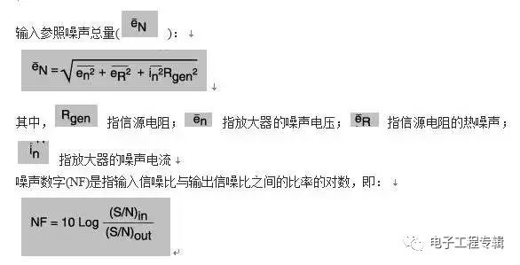
Both S and N in the above equation are power.
PDA Microphone Preamplifier Circuit Here we discuss how to design a mic preamp for PDAs. As mentioned above, we must understand that the source is the input preamplifier signal. First, we must know the following information:
Planned microphone type
Microphone output signal level
Microphone impedance and frequency of specified impedance
Gain regulation, the gain may be limited by the gain-bandwidth product of the op amp
Input signal frequency range
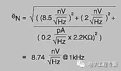
Noise specifications such as the specifications of a ceramic microphone are as follows:
Impedance: 2.2k (operating at 1kHz frequency)
Output signal: 200 (Vpp
Audio input frequency range: 100Hz to 4kHz
Thermal noise: 2nV / (Hz preamplifier gain index: 500 (non-inverted), the first stage can achieve 5 times the gain, the second level can reach 100 times the gain.
We quote Equation 1:
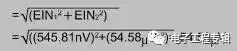
Equal Input Noise (EIN) = Total Input Reference Noise () × Input Frequency Range
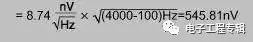
Output Noise = Equal Input Noise × Gain = 545.81nV × 5 = 2.73uV (for Level 1 Gain) or 545.81nV × 100 = 54.58uV (for Level 2 Gain). Total output noise of two amplifier stages
Signal-to-noise ratio level of 1 volt output voltage = 20 × log (1V ÷ 54.58uV) ≈ 85.3dB The total output noise of the circuit is approximately the square root of the sum of the mean rms values ​​of the root mean square of each noise source, and the output noise is usually Most of them come from sources with the most noise. The actual circuit is shown in Figure 2.
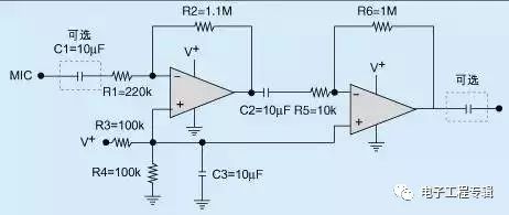
Figure 2 MIC preamplifier circuit diagram
Please note that this circuit is only suitable for single-supply design, where the input and output capacitors (C1 and C4) are only options, and engineers can choose according to the actual situation. Applicability depends on how the input and output of the user system are connected. If the microphone output is DC compensated, then a C1 input capacitor is required to block the DC signal. The output capacitor can also perform the same function. Most of the microphones currently on the market are based on 2k (high-impedance microphones and only a few hundred (low-impedance microphones). Both types of microphones can be designed with the above preamplifiers. High-impedance and high-output microphone preamps are more common. Simple, non-inverting or inverting amplifier configuration can be used. Because of its flat frequency response, no special equalization is required, and the input level is large, the amplifier has low noise requirements, but the high-impedance microphone has unknown noise. And the magnetic field is extremely sensitive. The low-impedance, low-output mic preamplifier can also use a non-inverting or inverting amplifier to amplify the input signal, and the frequency response and equalization requirements are roughly the same as those of the high-impedance, high-output preamplifier. The output level of the microphone is low, and engineers must pay attention to the use of low-noise op amps. For example, a low-noise op amp with better performance should produce lower input reference voltage noise, and the noise should not exceed 10nV/((Hz).
Analysis and Measurement of Intrinsic Noise in Operational Amplifier Circuits We can define noise as any unwanted signal in an electronic system. Noise can cause audio signal quality degradation and errors in accurate measurements. Board-level and system-level electronic design engineers hope to determine how much noise the design will have under worst-case conditions, and find ways to reduce noise and accurately determine the feasibility of their design. Noise includes both intrinsic noise and external noise, both of which affect the performance of electronic circuits. External noise comes from external noise sources, and typical examples include digital switching, 60 Hz noise, and power switching. Intrinsic noise is generated by the circuit components themselves, the most common examples being broadband noise, thermal noise, and flicker noise.
suzhou whaylan new energy technology co., ltd , https://www.whaylan.com