Electrocardiogram (ECG) is an important means of heart disease diagnosis. Routine electrocardiogram is a short-term electrocardiographic activity recorded by a patient's electrocardiograph in a resting position. Due to the great chance and suddenness of a heart attack, regular electrocardiogram examination is performed during the non-seizure period to obtain disease information The odds are very low.
Therefore, it is of great practical significance to extend ECG monitoring from the bedside and in the hospital to the home and realize real-time remote monitoring.
The rapid popularization of the Internet, especially the wireless network, has made the application of embedded technology increasingly mature. In addition, the importance of ECG monitoring for heart disease diagnosis also makes remote monitoring a real possibility.
This paper mainly studies and designs a set of practical portable mobile ECG monitoring system. Through this system, the patient's ECG signal can be wirelessly sent to the PC set up in the hospital through the GPRS network, or the ECG data can be stored in the system first, and then the high-speed playback can be achieved through USB.
The overall design of the system
The portable mobile ECG monitoring system designed in this paper is composed of ECG monitor, communication network and monitoring center (as shown in Figure 1). The working process is as follows:
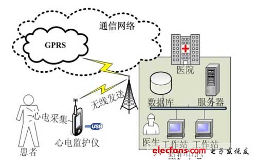
Figure 1: Overall block diagram of a portable ECG monitoring system
The ECG monitor is carried by the patient, and the user's ECG data can be collected at any time through the paste electrode, and amplified, filtered, A / D converted, and then stored in the serial flash memory. After storing the ECG data for a certain period of time, you can surf the Internet wirelessly via GPRS and use the wireless network to transmit the data to the host computer located in the monitoring center. It can also be directly connected to the host computer via USB for local high-speed playback.
This article will focus on the design of ECG monitors. Because it is a portable device, it must be designed to reduce power consumption, volume, and cost as much as possible. After repeated analysis and comparison, it was finally decided to use Z-World's industrial-grade control chip Rabbit3000 microprocessor as the main chip of the ECG monitor.
Although Rabbit3000 is an 8-bit microprocessor, its memory space can reach 1M and the main frequency can reach 22M. It has rich interface resources, a total of 40 parallel I / O port lines (shared with the serial port). In addition, the power consumption of this device is very low, the processor clock can be driven by the 32.768KHz oscillator, and power off the main oscillator. At this time, the current is about 100 μA, and the processor can still maintain the execution speed of 10,000 instructions per second.
System hardware design
In the overall hardware design, the Rabbit3000 high-performance microprocessor is used as the core, the external interface is used to expand 512K of parallel Flash and 512K of SRAM, the storage space reaches 1M, and the USB interface is expanded. The serial flash, A / D conversion, and wireless module MC35 are expanded using the serial interface. The following focuses on the hardware design of the wireless module and the USB module.
1. Wireless module MC35 hardware design
The wireless module is responsible for the wireless transmission of ECG data. In order to realize this function, this system adopts MC35 module of Siemens. This is the first GSM / GPRS module from Siemens to support GPRS. It is compact and easy to integrate into portable terminals. Connected through the serial port, use the AT command to control and data transfer to the module.
The MC35 module of Siemens has a 40-pin zero-insertion-force connector, which provides interfaces such as serial interface, audio interface, SIM interface, status pin, power interface, etc., through these interfaces with the SIM card holder and antenna And the main controller is connected. The serial interfaces TXD0 and RXD0 of the MC35 are connected to the serial port B of Rabbit3000, that is, the pins TXB and RXB (PC4 and PC5), to achieve communication with the MC35. The IGT pin of MC35 is its start pin and needs to be driven by an open-drain driver. And the port E of Rabbit3000 has very strong driving ability, so choose PE5 as the starting control line of MC35. In the power interface of MC35, there are power input pin, power output pin and charging pin, among which the charging pin can be used to charge the battery. This system uses battery power supply or external charging. as shown in picture 2.
Two points to note when designing are: This system uses battery power supply, because MC35 needs to provide a peak current of 2A in the upstream transmission, which will cause a sudden voltage drop, so a large enough capacitor should be added when designing the circuit to prevent the voltage from suddenly dropping ; When designing the SIM card circuit, you need to pay attention to the problem of electromagnetic compatibility, otherwise it will affect the communication effect of the MC35, and even cause the MC35 to not work properly.
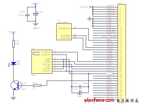
Figure 2: MC35 module hardware connection diagram
2. USB module hardware design
The USB module is responsible for completing the local high-speed playback of ECG data, which provides another means of data transmission. The usual serial port RS-232 only uses one line for data transmission, and USB transmission uses differential signals on the D + and D- lines to transmit data with the host, which fully guarantees the reliability of data transmission. This system uses NXP's PDIUSBD12 to achieve USB transmission.
PDIUSBD12 (hereinafter referred to as D12) is a very cost-effective USB chip from NXP, which fully complies with USB1.l version specifications. It is one of the most used chips in the USB1.1 protocol device. It is a pure USB interface chip and requires external microprocessor control.
This system uses the Rabbit3000 microprocessor to control the USB chip D12 to complete the USB transmission. At this time, D12 is a peripheral of the single chip microcomputer. The data transmission between D12 and Rabbit3000 is realized through 8-bit data lines, that is, the parallel data lines D0-D7 of D12 are directly connected with the data lines D0-D7 of Rabbit3000.
The INT_N pin of D12 is connected to Rabbit3000 multiplex pin INT0A, which is used as the external interrupt input of Rabbit3000. When D12 needs to operate, it uses the INT_N pin to issue an interrupt request, and Rabbit3000 immediately responds to the interrupt and operates it. RD_N and WR_N of D12 are connected to IORD and IOWR of Rabbit3000, respectively, to control the direction of data transmission. RESET_N of D12 is connected to the multiplexing pin PE4 of Rabbit3000. Rabbit3000 can use this pin to send a low level to D12. After RESET_N is set to low level, D12 will automatically reset. The CS_N of D12 is connected to the multiplex pin PE7 of Rabbit3000, which can be used to control the chip selection. As shown in Figure 3.
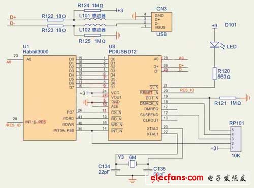
Figure 3: PDIUSBD12 module hardware connection diagram
D12 has two data bus modes: multiple address / data bus mode and single address data bus mode. This system adopts single address data bus mode, connects D12's ALE to ground, and A0 is connected to Rabbit3000's address bus A0. Under the premise that the chip select signal is valid (ie PE7 = 0), when A0 = 1, the CPU sends a command to D12 ; When A0 = 0, the CPU writes data to D12 or reads data from D12. Therefore, address 0xE001 is the address for sending commands, and address 0xE000 is the address for reading and writing data.
Off Grid Solar System,5Kw Off Grid Solar Energy System,Off Grid Solar System For Home,Off Grid Solar System Panel
Jiangsu Stark New Energy Co.,Ltd , https://www.stark-newenergy.com