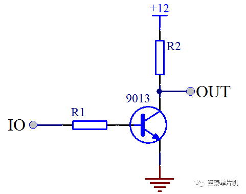
Triodes are widely used in digital circuits for their switching characteristics, primarily for two main applications: control and drive. The first application involves using the triode as a switch to manage power or signals indirectly. For example, as shown in Figure 3-7, we can control the backlight of a display by adjusting the base of the triode via a microcontroller. This is a common practice and easy to understand. Another control application is managing voltage transitions. Suppose your microcontroller operates at 5V, but you need to interface with a 12V system. Directly connecting the 12V to the MCU’s IO port could damage it. To avoid this, a triode is used. Since the triode can handle higher voltages than the MCU’s IO, it allows the 5V signal from the microcontroller to control a 12V circuit, as illustrated in Figure 3-8.
 Voltage Conversion
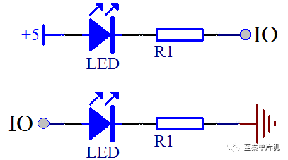
In Figure 3-8, when the IO port outputs a high level (5V), the triode turns on, causing the output (OUT) to go low (0V). When the IO port is low, the triode turns off, and the pull-up resistor R2 pulls the OUT pin to a high level. This setup enables low-voltage control of high-voltage systems. The second major use of triodes is in driving applications, where they provide greater current capability than the microcontroller's IO ports. Let’s look at the comparison between two LED control circuits in Figure 3-9.
 LED Small Light Control Method Comparison
In the upper part of Figure 3-9, the LED behaves as expected—when the IO is high, the LED turns off; when the IO is low, the LED turns on. However, the lower circuit seems different. Based on similar logic, one might expect the LED to light up when the IO is high, but that’s not the case. The reason lies in the limited current output of the MCU’s IO port. Typically, an IO pin can only supply tens to hundreds of microamps, which is far too small to light an LED effectively. To overcome this, a triode is used to amplify the current. Our board uses transistors capable of handling up to 500mA, making them ideal for such tasks, as shown in Figure 3-10.
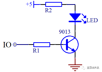
In Figure 3-10, when the IO is high, the transistor turns on, allowing a much larger current to flow through the collector, lighting the LED. Even though some might consider using the low-level output to directly drive the LED, the current capacity of the IO port is still insufficient. According to the STC89C52 datasheet, the total current per IO should not exceed 6mA, and the overall MCU current should be under 50mA. If multiple LEDs are connected, the current requirement increases significantly. For instance, if eight LEDs are lit simultaneously, each drawing around 8mA, the total current would be 64mA, which exceeds the MCU’s limits. Reducing the current-limiting resistor to 1kΩ would lower the current to about 3mA per LED, totaling 24mA, but this would make the LED too dim. In practical engineering, it's not advisable to directly connect multiple LEDs to the MCU’s IO port.
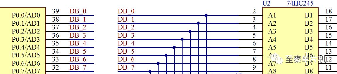
To address this, driver ICs like the 74HC245 can be used. These ICs act as current buffers without any logic functions. The 74HC245 can handle up to 70mA, which is more than enough for most LED arrays. As shown in Figure 3-13, the 74HC245 is placed between the MCU and the LED array to ensure sufficient current delivery. It also includes a decoupling capacitor (0.1µF) and pull-up resistors (R10–R17) to stabilize the signal. The direction pin (DIR) is set high, allowing data to flow from the A side (connected to the MCU) to the B side (connected to the LEDs). The OE (output enable) pin is held low to activate the buffer function. If OE is high, the chip is disabled, regardless of the DIR setting.
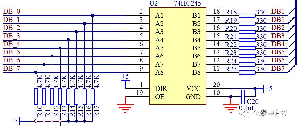
Some may wonder why both a triode and a driver IC are used together. The answer lies in circuit design principles. Current must flow through a complete path, and any bottleneck in the circuit will limit the current. Just like water flowing through pipes, if one section is too narrow, the entire flow is restricted. The 74HC245 helps eliminate the bottleneck caused by the MCU’s limited current output, ensuring stable operation of the LED array. This approach ensures that the system remains reliable even under heavy load conditions.
Core i9 Mini PC,,Portable Mini Pc,Mini Pc I3
Shenzhen Innovative Cloud Computer Co., Ltd. , https://www.xcypc.com