The article first explains the basic structure of the variable frequency speed control system, the basic principle of SVPWM algorithm, parameter calculation and implementation method, then gives the specific calculation process of SVPWM algorithm on DSP2407. Finally, the experiment verifies that the whole system can work normally and accurately. . At the same time, based on MATLAB/Simulink, the simulation model is designed to simulate the algorithm. The simulation waveform is basically consistent with the theory, which confirms the feasibility of the scheme.
1 Introduction
With the continuous updating of new power electronic devices, the frequency conversion speed regulation technology has been greatly developed. After more than half a century of development, enrichment and improvement, the frequency conversion speed regulation technology has become the most widely used speed regulation method.
However, the traditional SPWM technology has some shortcomings. The SPWM technology focuses on making the output voltage of the inverter as close as possible to the sine wave. However, the motor needs to form a circular rotating magnetic field in the air gap to generate a constant torque. These are SPWM. The technology is not easy to do, and the SVPWM technology considers the inverter and the motor as a whole, and controls the voltage space vector so that the motor obtains a circular rotating magnetic field with a constant amplitude, the rotating torque is stable, and the inverter output harmonics Small, harmonic loss is small, so its application is increasingly widespread.
2. Overall structure of the system
The variable frequency speed control system consists of three parts: the inverter, the motor and the control system, and sometimes the load. The overall structure is shown in Figure 1.
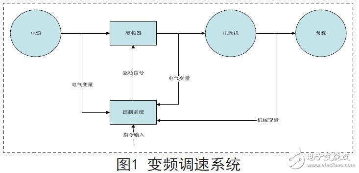
The frequency converter is an AC power source that can change the frequency. The control system is mainly composed of a controller and a measuring instrument such as current and speed, and is used for adjusting the rotation speed of the motor and controlling the torque of the motor according to a given command to complete the transmission task. The motor is mainly an asynchronous motor, and a synchronous motor is used in a few occasions. Loads are all kinds of working machines and equipment used to complete various production tasks.
3.SVPWM algorithm principle and implementation
The working principle of SVPWM is to regard the inverter and the motor as a whole. According to the relationship between the motor flux linkage and the voltage, the 8 basic voltage vectors are used to synthesize the desired output voltage vector to realize the AC motor frequency conversion speed regulation.
3.1 Two-level inverter
Generally, the input of the low-voltage inverter is a single DC power supply. When this constant DC voltage is pulse-width modulated, the output is a PWM wave of a certain amplitude. If the DC voltage is set to zero voltage at the low voltage node, the certain PWM wave obtained by the inverter has only two levels, that is, 0, so the inverter is called a two-level inverter, as shown in the figure. 2 shows:
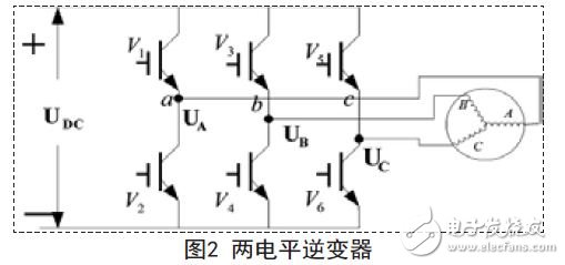
The inverter uses six IGBTs (insulated gate bipolar transistors) V1-V6 to form a three-phase inverter bridge, V1, V3, and V5 are common anode groups, and V2, V4, and V6 are common cathode groups, and each bridge arm is two. The IGBTs are connected in series, and the three-phase wiring is taken out from the connection point, and one cycle is divided into 360°, and V1-V6 are sequentially turned on at an electrical angle of 60° apart, and each IGBT is turned on by 180°. At any one time, three IGBTs are turned on, and the other IGBT of the same arm must be turned off, so that the working inverter can output three-phase alternating current to the three-phase load.
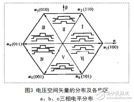
Under normal circumstances, the two-level inverter is switched every 60° during the six-shot operation. There are 8 kinds of switch states, which can be expressed as 100, 110, 010, 011, 001, 101 according to a, b, c phase sequence. 000, 111. Each of the switch state output synthesized voltage space vectors out u is denoted as u1, u2, u3, u4, u5, u6, u0, u7, respectively, and is collectively referred to as a basic vector, where u1-u6 are vectors having output values , called non-zero vector, u0, u7 no voltage output, called zero vector. The spatial distribution of the eight voltage vectors is as shown in Figure 3 above. Each vector can be divided into six sectors (I-VI). If the voltage vector is switched counterclockwise, the motor will rotate forward. If it is switched clockwise, The motor is reversed.
Power System Optical Fiber Cable
Power System Optical Fiber Cables Factory, Power System Optical Fiber Cables Grid, Simplex Cable,Power System Optical Fiber Cable,Optical Fiber Cable,Large Number Of Cores
Shandong Qingguo Optical Fiber Co., Ltd. , https://www.qgfiber.com