Matching of cross-type transmitting antenna 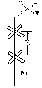
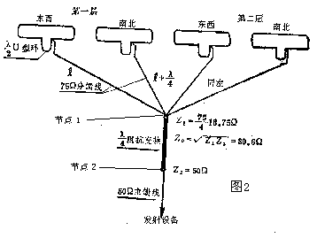 In some small and medium-power high-frequency transmission equipment, multi-layer cross-type half-wave folded oscillator transmission antennas are usually used. The characteristic of this type of antenna is its simple structure and convenient installation. Its disadvantages are its low gain and relatively narrow bandwidth. Here, the double-layer cross-type antenna is used as an example to explain its connection principle. Figure 1 shows the structure of this type of antenna. We know that the input impedance of a half-wave vibrator is balanced 300 ohms, and the output impedance of the transmitting device is usually 50 ohms unbalanced, so first we must balance the 300 ohms equivalent to the oscillator. Convert to 75 ohms unbalanced (for the conversion principle, please refer to my previous articles), then two 75 ohm coaxial cables with length λ (wavelength) (called sub-feeders) will be two layers of east-west oscillators Use two 75-ohm cables of length λ + λ / 4 to connect the north-south vibrators in the upper and lower layers into a node 1 (as shown in Figure 2). The impedance of node 1 is 75/4 = 18.75 ohms, because The output impedance of the transmitting device is 50 ohms, so impedance conversion must also be performed. We use
 ![]() This formula is used for calculation, where Z0 is the required impedance characteristic of the matching cable of λ / 4 length, Z1 is the impedance of node 1, and Z2 is the output impedance of the transmitting device (node ​​2). Calculated
This formula is used for calculation, where Z0 is the required impedance characteristic of the matching cable of λ / 4 length, Z1 is the impedance of node 1, and Z2 is the output impedance of the transmitting device (node ​​2). Calculated ![]() To this end, we can use a 50-ohm cable with a length of λ / 4 and a 75-ohm cable of the same length in parallel to approximate replacement.
To this end, we can use a 50-ohm cable with a length of λ / 4 and a 75-ohm cable of the same length in parallel to approximate replacement.
Why should the east-west and north-south subfeeders differ by λ / 4? This is to make the electromagnetic wave uniformly radiated in the horizontal plane. As the length of the sub feeder, its radiation pattern in the horizontal plane is shown in Figure 3. From the figure, it can be seen that the radiation field is in the southwest. 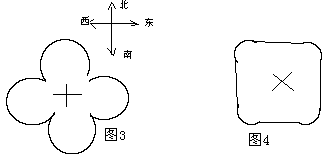 Northeast, southeast, and northwest are weaker. If the north-south and east-west oscillators differ in phase by π / 2 on the feed, then the radiation field formed is a rotating magnetic field, and the radiation pattern is as shown in the figure As shown in Fig. 4, it can be seen from the figure that the radiation field is relatively uniform in all directions. According to the principle of the transmission line, to generate a phase difference of π / 2, it is only necessary to increase the sub-feeder in a certain direction (such as north-south) by λ / 4. . Thinking draft
The measurement method of the antenna standing wave ratio In the antenna system, whether the antenna and the device are well connected is often measured by a parameter called the standing wave ratio. When the standing wave ratio is 1, it means that the antenna system is well matched. Reflection, the larger the number, the worse the matching condition, and the greater the reflected wave in the system. So how do you measure the VSWR of the antenna? Here I will introduce a simpler method to you.
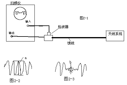
To measure the standing wave ratio, a frequency sweeper is needed. The connection method is shown in Figure 2-1. First, short-circuit the terminal of the feeder (near the antenna system). At this time, the signal output by the frequency sweeper forms a total reflection at the terminal of the feeder. Observe the total reflection waveform as shown in Figure 2-2. The maximum amplitude of the curve is a, and then connect the antenna to the terminal of the feeder. At this time, the maximum amplitude observed on the frequency scanner within the operating frequency range is b. As shown in Figure 2-3, First find the reflection coefficient P = b / a, then use the formula S = 1 + P / 1-P to find the standing wave ratio, where S represents the standing wave ratio. Thinking draft
The electrical length of the cable 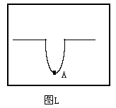 A parameter called electrical length (unit: MHZ) is commonly used in transmission lines to measure the electrical performance of cables. When the factory produces cables, due to the manufacturing process, the electrical specifications of each batch of cables are different. For example, two cables with the same physical length have the same electrical performance for the same high-frequency signal. Not the same, so the concept of electrical length was introduced. It reflects the characteristics of the cable to a certain frequency signal within a unit of physical length. This parameter is particularly important in the feed system for making transmit antennas. For example, the sub-feeder cables in the article "Mating of Double-Layer Cross-type Transmitting Antenna" published by me, when the physical length is the same but the electrical length is not the same, the actual impedance of the sub-feeder will shift and cause The additional phase shift makes it difficult to match the entire antenna system.
So how to detect the electrical length of a cable? The specific method is this. For example, the center frequency of the transmitting antenna is F, the corresponding wavelength is λ, and a cable with a physical length of λ / 2 is intercepted to short-circuit its terminal to form a total reflection of the signal. The frequency meter performs the test and adjusts the center frequency of the output of the frequency sweeper to produce a depressed waveform on the screen of the frequency sweeper (as shown in Figure L). This depressed wave is the reflected waveform of the cable. From the long-line theory, we know that for a certain frequency signal, the transmission line with a short-circuited terminal is at the maximum λ / 2 from the terminal, and its reflected wave current has the largest amplitude, so at this time point A (that is, the frequency corresponding to the peak) ) Is the electrical length of this cable. If the frequency indicated by the frequency scale at point A is equal to F, it means that the electrical performance of this cable is up to the standard. If it is not equal to F, it means that there is a difference in the electrical performance of the cable. It must be corrected (physical length).
For cables with the same characteristics, when their physical lengths are the same, their electrical lengths are also the same; when their characteristics are not equal, the physical lengths of the cables are the same and their electrical lengths are different, so we can use the electrical lengths This indicator measures the consistency of cable performance. Thinking draft
 Directional coupler In many high-frequency transmission equipment, a directional coupler is often inserted in the path from the final power amplifier to the transmission antenna to measure the transmission power of the transmission equipment or the reflected power of the antenna. Let me introduce this directional coupler Works.
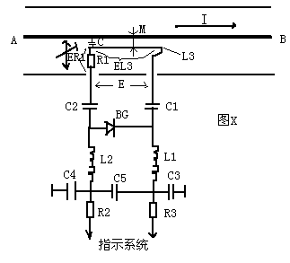
Figure X is the principle diagram of the directional coupler, where A and B are the inner conductors of the main feeder cable, and a coil L3 is placed near the inner conductor, where C is the distributed capacitance between L3 and the inner conductor. When a radio frequency signal is fed in, current I flows through A and B, where E is the RF voltage between the inner and outer conductors. Due to the presence of distributed capacitance C, then a current in the inner conductor flows to the outer conductor through C and R1. This current will produce a mutual inductance voltage EL3 on R1. Obviously, the output voltage across ab is E = ER1 + EL3. In manufacturing, we appropriately select L3 and R1 and change C and mutual inductance coefficient M during debugging, so that in a The output voltage E in the direction is the maximum (that is, ER1 and EL3 are added in phase), while in the other direction, the output of E is extremely small (that is, ER1 and EL3 are subtracted in phase), In this way, we have realized the role of directional coupling. The output voltage E is detected by BG1 and sent to the indicator system, so that we can read the actual power sent by the machine to the antenna on the indicator system. Thinking draft

Follow WeChat

Download Audiophile APP

Follow the audiophile class
related suggestion
'+ data.data.username +' '; dom + ='
APM 80V Dc Switching Power Supply is applicable to automobile electronics product testing sector. It also covers the 48v Power Supply. APM power supply is built-in 12V DIN4089 automobile starting voltage waveform, be able to simulate automobile engine electronic performance test;Meanwhile ,the built-in 12V ISO-16750-2 engine start test waveform enable simulation of voltage drop test waveform and restoration function test waveform.
Some features of the DC Power Supply as below:
- Ultrafast respond time and high efficiency.
- Accurate voltage and current measurement capability
- Constant Power and wide range of voltage and current output
- Equips with LIST waveform editing function
- Compliant with SCPI communication protocol
- Support RS232/RS485/LAN/USB (standard) ,GPIB (optional)
- Master/Slave parallel and series operation mode for up to 10 units
- Full protection: OVP/OCP/OPP/OTP/SCP
- Voltage drop compensation by remote sense line.
- Have obtained CE,UL,CSA,FCC.ROHS
80V Dc Power Supply,Variable Dc Power Supply,Laboratory Power Supply,Modular Power Supply
APM Technologies (Dongguan) Co., Ltd , https://www.apmpowersupply.com