In recent years, grid-connected transformation technology applied to renewable energy has formed a research hotspot in the field of power electronics technology. Grid-connected converters have broad development prospects in renewable energy distributed energy systems such as solar photovoltaics, wind power generation, etc. The important application mode of solar and wind power generation is grid-connected power generation, and grid-connected inverter technology is the key technology of solar photovoltaic grid-connected power generation. The inverters used in photovoltaic grid-connected power generation systems are mainly based on the following technical characteristics: wide DC input range; maximum power tracking (MPPT) function; the phase and frequency of the output current of the grid-connected inverter are synchronized with the grid voltage , Waveform distortion is small, meet the requirements of power grid quality; with island detection and protection function; inverter efficiency up to 92%, can be run in parallel. The inverter's main circuit topology directly determines its overall performance. Therefore, it is important to develop a simple, efficient, and cost-effective circuit topology.
1. Inverter principle
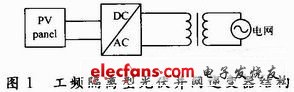
The design is a large-scale photovoltaic grid-connected power generation system. According to the literature, the power frequency isolated photovoltaic grid-connected inverter structure is generally selected, as shown in Figure 1. The DC power output by the photovoltaic array is converted into AC power by the inverter, and then integrated into the power grid after being boosted and isolated by the transformer. The core of the photovoltaic grid-connected power generation system is the inverter, and the power electronic device is the foundation of the inverter. Although the process level of the power electronic device has been greatly developed, it must be produced to meet the high frequency, high voltage and low EMI as possible. The high-power inverter still has great difficulties. Therefore, research on the topology of large-capacity inverters is a representative solution. As an energy converter between a solar photovoltaic array and an AC grid system, its safety, reliability, inverter efficiency, manufacturing cost and other factors play a decisive role in the development of photovoltaic inverters, which determines the investment and income. Most mainstream photovoltaic converters in the market use voltage source converters. Because of the current source output characteristics of photovoltaic cells, in order to meet the characteristics that the DC voltage of the photovoltaic cells may change greatly, the technical solution of two-stage conversion is used, which leads to conversion Reduced efficiency. High-power current source conversion technology, because of the high price and low reliability of the forced current snubber capacitor, limits the application of current source converters. The full-control characteristics of the DC current and voltage of the injection current source converter make the DC power emitted by the photovoltaic cell complete only by one-stage conversion. This feature makes the current source converter likely to be an efficient photovoltaic conversion technical solution. .
1.1 Two-level inverter
Traditional inverters are usually also called two-level converters, and grid-connected inverters generally use bridge circuits. This topology is relatively simple. Solar photovoltaic cells have the characteristics of current source type. After the photovoltaic array is connected in series with a large inductance, it is equivalent to a current source. In this way, it is connected to the power grid and is called current source grid connection. In order to improve the grid-connected current, a filter capacitor needs to be added on the AC side, and the photovoltaic cell must be connected to the corresponding DC bus with a series inductance. Due to the presence of large inductance, the DC loop current is not easy to change. If the inverter input current is not stable when the inverter is switched, it will easily produce a high di / dt, affecting the safe operation of the inverter.
1.2 Multilevel injection current source inverter
The concept of harmonic injection has been used in power converters for more than half a century. However, harmonic injection is used in power converters as a method of reducing harmonic content. The amplitude of the multi-stage injection current is matched with the working conditions. The additional thyristor trigger control and the use of ripple voltage to achieve natural commutation, the frequency and phase of the injection current are synchronized with the power supply. Based on the fixed amplitude relationship between DC current and injected current, the optimal harmonic suppression under various working conditions is guaranteed, and the quality of AC current waveform and DC voltage waveform is further improved. In the literature, a new concept of DC current injection is proposed, and it is found that an injection current of 6 times the fundamental frequency can be used to completely suppress harmonics when used in a 12-pulse current source converter. The research method of unconventional system is to find the amplitude of the injected current waveform, so as to achieve the purpose of minimum harmonic distortion rate. And through rigorous mathematical analysis, this idea is summarized and the ideal injection waveform that can completely eliminate the harmonics of the AC measured output waveform of the standard 12-pulse current source converter is derived. 12-pulse current source converter, the working mode of the main circuit is the same as the ordinary three-phase full-control bridge converter, the six thyristors in each bridge are triggered and turned on sequentially at 60 ° intervals, and each main bridge switch is turned on 120 °. In this way, for two parallel three-phase fully controlled bridges, the switch on one bridge arm is triggered every 30 °, and two switches are turned on at any time. It does not require the AC system to provide the commutation voltage, and it can be operated as a rectifier or an inverter in synchronization with the AC system. When the active power is transferred from the AC system to the DC system, the device works in a rectified state, and when the active power is transferred from the DC system to the AC system, the device works in an inverter state. The DC voltage of the multi-level injection current source inverter (MLCR-CSC) can be positive or negative. The converter needs to use switching devices with symmetrical characteristics, that is, devices with bidirectional voltage blocking capability and unidirectional current flow capability. Therefore, IGBT can not be directly used in MLCR-CSC, diode and IGBT in series can meet this performance requirement, but the series connection will cause additional power loss. Due to the relatively low switching frequency of MLCR-CSC, thyristors are suitable for high-power MLCR-CSC. Due to the existence of the DC-side inductance, the DC current flows in one direction, and the polarity of the DC voltage may change instantaneously, so the switching device required by the multi-stage injection current source converter should have bidirectional voltage blocking capability and unidirectional current circulation capability.
2. Experimental simulation
2.1 Model building of solar cell
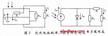
The equivalent circuit of the photovoltaic cell according to the principle of literature is shown in Figure 2. On this basis, a DC power supply with an output of 0 to 450V is built in PSCAD. The model is shown in Figure 2. The simulation model selects typical photovoltaic parameters, and the component model is YL85 (17) 1010 & TImes; 660. The main parameters are: output peak power 85W, peak voltage 17.5V, peak current 4.9A, open circuit voltage 22V, short circuit current 5 .3A. The photovoltaic array is required to output 5000W, and it can be estimated that the connection mode of the photovoltaic module is 20 strings and 3 parallels.
From the simulation model of the photovoltaic array in FIG. 3, the IU characteristic curve and the PU characteristic curve are obtained as shown in 4.
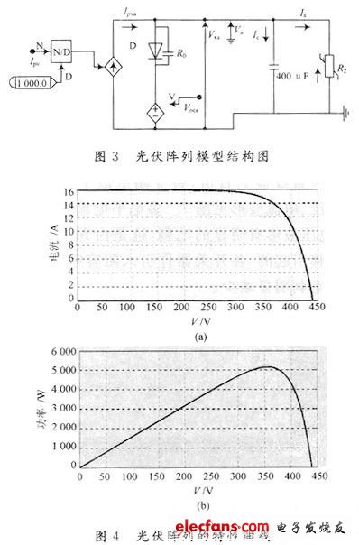
The maximum power obtained by calculation is 5.1kW, which is basically consistent with the power output by the model, and other parameters of the input are also basically consistent, so it can be used in engineering practice.
2. 2 inverter topological circuit
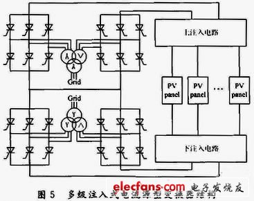
In this topology (see Figure 5), the main control bridge uses a two-phase three-phase full bridge connected in series to form a 12-pulse current source converter. The main bridge is composed of 24 converter valves, and each switch valve is composed of a thyristor. The AC side is formed by a series connection of transformers. The transformers are connected by Y / Y and Y / △ respectively, and the transformation ratios are Kn: 1 and Kn: respectively. The trigger pulse constituting the 6-pulse converter connected to Y / △ lags behind the 6-pulse converter connected to Y / Y by 30 °, so that the output of the two converters is in phase with each phase voltage on the primary side of the transformer. The injection circuit in the figure is composed of thyristors and diodes connected in series or anti-series. The switch connected to the upper bridge is the reverse connection of the thyristors and diodes. In operation, the upper bridge is also injected with the ideal current waveform to make the waveform output ideal.
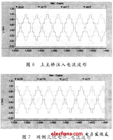
In Fig. 6, the current waveforms of the upper and lower corresponding three-phase bridges of the main bridge are equal and the phase difference is 15 °. The inductance branch current is a DC with a small amount of ripple, and the average value of each branch current is IDC / 6. See Figure 7 for AC voltage and current waveforms. The sineness of the multi-level current waveform is better, and the voltage waveform has obvious glitches. This is caused by the inductive energy transfer when the switch is switched. After each switching device is introduced into the RC absorption circuit, the voltage glitch can be significantly reduced.
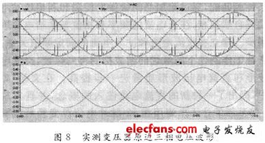
In Figure 8, CH1 is the A-phase voltage waveform; CH2 is the B-phase voltage waveform; CH3 is the C-phase voltage waveform. The conclusion is that some glitches are superimposed on the sinusoidal waveform of the three-phase voltage, which is consistent with the simulation.
3. Experimental conclusion
Determination of the best combined control scheme for power electronic switches of each injection branch. Multiple injection branches have multiple switch combination schemes. How to realize the conversion requirements with a switch combination scheme of lower complexity is one of the main technical difficulties of the research. In the simulation, using PSCAD to do 6-level current injection research, proved that the system can get the ideal output waveform without adding filters and using PWM technology. It is precisely because the device has a very low harmonic distortion rate and low switching loss, so the device is very suitable for high-power applications.
Fiber Optic Splice Closure is mainly used for protecting the fiber optic junction between two cables and reserve a section of fiber optic for maintenance in the box. The box has good leak-proof, anti-water and damp-proof feature and its power line is corrosion resistant.
There are two types of the junction box, central and terminal one. The central type is used in the central part if the line to protect the tow butted cables while the terminal type is used in the end of the line for branching in the cable line or protecting the connection of the fiber optic in the cable and the jumper.
Fiber Enclosure,Fiber Enclosure Outdoor,Optical Vertical Closure,Optical Inline Closure
Chengdu Xinruixin Optical Communication Technology Co.,Ltd , https://www.xrxoptic.com