In the near future, automotive radar systems will become more and more popular, and they provide many comfortable and safe applications. Short-range radars range from a few centimeters to 30 meters and can be used for blind spot detection, reversing assistance or parking space measurements to guide car self-parking. The long-range radar can reach 250 meters and is used to initiate adaptive cruise control to keep the car and front speed consistent. In addition, it can activate more important functions such as collision warning, emergency braking, and even impact warning detection systems, which may trigger seat belt tension meters or other active or passive safety functions. Obviously, with these latter features, the electronic control system needs to achieve the highest level of functional safety, because this system will eventually turn or brake the car without driver intervention.
The development and innovation of this radar technology is continuously applied in other applications such as mobile industrial computers, cranes, factory safety equipment, etc., and this application field requires strict security protection. Coupled radar and machine vision can also create a powerful combination that complements each other to create a more accurate and reliable system. When machine vision is blocked, the radar can operate in rain, fog and dirt. In addition, the radar can further extend its detection range and detect events in the indirect line of sight. A system that combines machine vision with radar and some smart sensor fusion algorithms can take advantage of the benefits of these two sensing technologies.
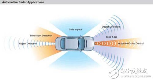
Figure 1: Automotive radar application
77 GHz radar technology
In the collision warning system, the signal from the 77 GHz transmitter will be reflected by objects in front of the body and then captured by multiple receivers distributed throughout the body. The transmitter emits a frequency modulated continuous wave signal, that is, in a fixed period of time, the frequency changes up and down with a typical triangular wave signal. Since radio waves propagate at a constant speed of light, the propagation distance can be calculated by measuring the frequency difference between the transmitted wave and the received wave (i.e., the frequency slope as a function of time). The velocity measurement uses the Doppler effect, that is, the observed reflected signal frequency is different from the emitted frequency.
The radar system is not a new highlight. The new highlight is that automakers want to build the system into mid-size cars in the last few years, so the system must be low-cost, high-quality. This means a big shift from expensive professional radar systems to standard automotive equipment types. The challenge is to reduce the cost while actually improving the quality of the product and reducing the number of parts per million pieces. This shift is shown in the “Quality and Cost Marketing Value Mapâ€.
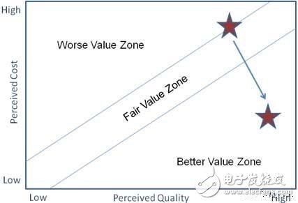
Figure 2: Marketing Value Map
This marketing value map shows the transition from a high-cost, good-quality system to a low-cost, higher-quality system. In order to achieve this goal, we must deal with many challenges.
Radar cost and quality challenges
Conventional radar uses a rotating antenna. This is also the principle of object space mapping. This may be suitable for large systems with expensive control systems, but certainly not for mass production of automobiles. One solution to eliminate rotating antennas is to use phased arrays or patch antennas for multi-channel transmit and receive channels. The air separation antenna will receive a reflected signal with a slight time difference. This difference is then used to reconstruct the position of the object without moving the antenna. A disadvantage of such a patch antenna is that multiple transmit and receive channels are required to connect the antenna. A typical system will employ four similar transmit antennas and 16 receive antennas. However, from an economic point of view, it is not feasible to repeat 16 receiving circuits and 4 transmitting circuits.
Then another innovation comes in handy. Instead of using RF differential circuits, Freescale has developed a dedicated RF BiCMOS process that is capable of integrating 77 GHz RF circuits onto a single chip. Beginning with the development of the high-performance SiGe:C (silicon germanium carbon) 180nm process, Freescale has also developed a dedicated 300GHz Fmax RF transistor capable of processing 77GHz radar signals on the chip. Combined with analog and digital CMOS circuitry, this process supports full integration of multi-channel 77GHz system-on-chip. Therefore, on-chip integration can offset multi-channel overhead costs.
Advanced packaging technology
Having a 77 GHz solid state silicon process is a huge asset, but processing and reporting it on a printed circuit board is another challenge. Traditional package parasitic impedances can destroy signal information at high frequencies. One way to deal with this problem is to solder bare chips to a dedicated PCB using precision wire bonding techniques instead of using typical packages and higher cost wave soldering techniques. The new advanced packaging technology called "RCP (Reassignment Chip Package)" comes in handy.
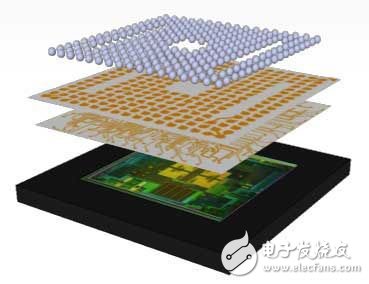
Figure 3: Layers in the RCP package
RCP uses a thick lithography technique instead of a PCB-type material to mount a copper interconnect layer on a chip or multi-chip system. This substrateless packaging technology has lower capacitance and inductance parasitic behavior. High-frequency signals can be routed at 77 GHz through this package with acceptable performance compared to the bare die soldering process. The advantage is that the complete set of tools for conventional PCBs can be used to solder this part, which means low cost processing.
With this process and packaging technology, Freescale continues to design integrated transmitter and receiver radar circuits.
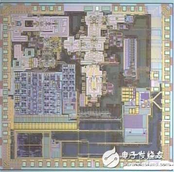
Figure 4: 77 GHz radar transmitter bare chip
The transmitter integrates a 77 GHz frequency synthesizer, a half-frequency voltage-controlled oscillator, a 10 GHz cross-link phase-locked loop, a power amplifier, and a 28-bit sigma-delta modulator. This is accompanied by specific ESD protection (RF and DC) and digital control via the SPI interface.
At the receiving end, we integrated a typical four receive channels and a local oscillator at 38 GHz, as well as an output differential IF. A typical noise figure of 13dB is achieved without the need for a low noise amplifier. This helps to maintain low power consumption and high linearity.
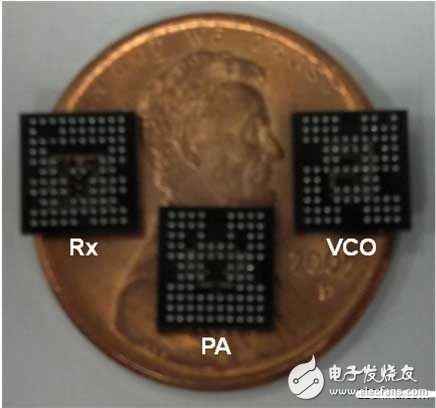
Figure 5: RCP package radar chipset
UV Germicidal Light Air Purifier
Uv Air Purifier,Uvc Air Cleaner,Uv Germicidal Lamp,Air Duct Uv Light
Dongguan V1 Environmental Technology Co., Ltd. , https://www.v1airpurifier.com