As an electronic engineer and technician, I believe that everyone is familiar with MOSFETs. When engineers are selecting a specific type of MOSFET, the first thing they look at is the datasheet. But once you have this document, which can span dozens of pages, how do you make sense of it all?
The purpose of this article is to share my understanding of MOSFET datasheets and some insights. If there are any mistakes or areas that need improvement, please feel free to point them out. I welcome your opinions and hope we can learn together.
PS: 1. The content/datasheet in the following sections will be referred to as "datasheet".
2. The data about MOSFET datasheets in this article comes from the Infineon IPP60R190C6 datasheet.
1. VDSThe first electrical parameter on the datasheet is V(BR)DSS, also known as the breakdown voltage between drain and source. This is one of the most critical parameters for MOSFETs.
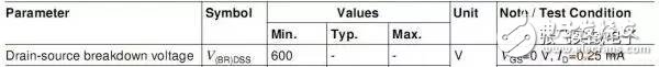
The minimum value of V(BR)DSS is 600V. Does that mean the MOSFET can safely operate under voltages below 600V? Many people might say yes, but the correct answer is no.
This parameter is specified under certain conditions. The minimum value of 600V is measured at Tj=25°C. However, as temperature changes, so does the breakdown voltage. For example, if the ambient temperature drops to -40°C, the V(BR)DSS value could be lower than 560V, which means 600V would exceed the withstand voltage.
Therefore, when using a MOSFET, it's important to include a safety margin. One reason is to account for the reduction in V(BR)DSS at low temperatures, and another is to handle voltage spikes during switching operations.
2. ID
MOSFETs were initially labeled with values like 20N60, but over time, the naming convention shifted to include Rds(on) and voltage ratings (e.g., IPx60R190C6, where 190 represents Rds(on)).
Understanding the relationship between ID and Rds(on) is essential. Before diving into that, let’s discuss the package and junction temperature:
1). Package: Factors that influence MOSFET selection include power dissipation, thermal performance, creepage distance, parasitic effects, and space constraints.
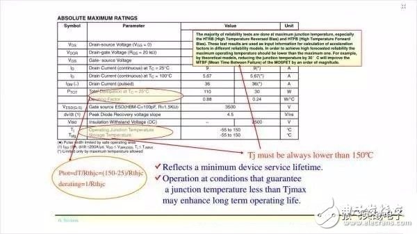
2). Junction Temperature: The maximum junction temperature Tj_max is typically 150°C, and it's recommended not to exceed 70–90% of this in practical applications.

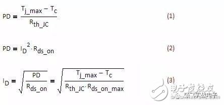
Back to the topic: the relationship between ID and Rds(on) depends on the thermal resistance of the package and the losses caused by current flow. This interaction determines the safe operating range of the device.
I came across a document today that mentioned the lifetime of a MOSFET is highly dependent on temperature. (See the red box below)
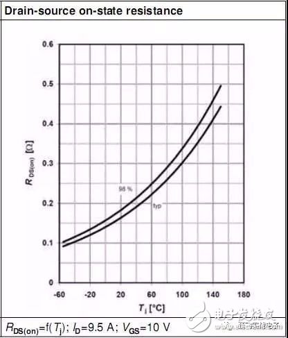
As shown in the graphs, Rds(on) increases with junction temperature, making it a positive temperature coefficient. This characteristic makes it easier to use MOSFETs in parallel configurations.
4. Vgs(th)
Vgs(th), or the threshold voltage, is a key parameter. It has a negative temperature coefficient, meaning it decreases with increasing temperature. While many engineers are aware of this, few pay close attention to its implications, especially in low-voltage MOSFETs.
For example, the BSC010NE2LS has a Vgs(th) of 1.2V to 2V at room temperature, but it can drop to as low as 0.8V at lower temperatures. A small gate spike could accidentally trigger the MOSFET, causing system failure.
So, when working with low-voltage MOSFETs, it's crucial to consider the negative temperature coefficient of Vgs(th).
5. Ciss, Coss, CrssMOSFETs have parasitic capacitances, including Ciss (input capacitance), Coss (output capacitance), and Crss (reverse transfer capacitance). These values vary with VDS and play a significant role in switching performance.
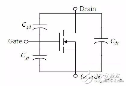
In LLC topologies, reducing dead time improves efficiency, but too little dead time can prevent Zero Voltage Switching (ZVS). Choosing a MOSFET with smaller Coss at low VDS can help achieve ZVS more easily, allowing for shorter dead times and improved efficiency.
6. Qg, Qgs, Qgd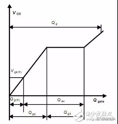
From this figure, we can see that Qg is not equal to Qgs + Qgd. Additionally, higher Vgs leads to larger Qg, which increases drive loss. Therefore, selecting a MOSFET with lower Qg is beneficial for reducing switching losses.
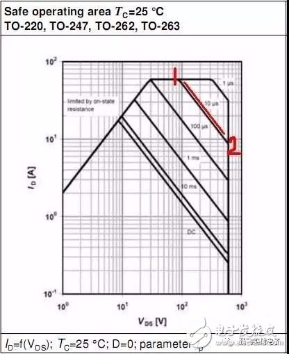
7. SOAThe Safe Operating Area (SOA) curve is divided into four regions:
1). Rds(on) Limit – defined by the maximum allowable current at a given voltage and junction temperature.
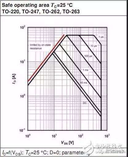
2). Maximum Pulse Current – limits the peak current the MOSFET can handle.
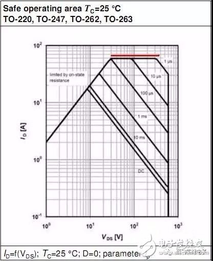
3). VBR(DSS) Breakdown Voltage – the maximum voltage the MOSFET can withstand.
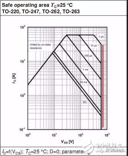
4). Maximum Loss Limit – defines the maximum power the MOSFET can dissipate without overheating.
To convert SOA curves from 25°C to other temperatures, transient thermal resistance (ZthJC) must be considered. This allows us to calculate the actual junction temperature under different operating conditions.
8. AvalancheAvalanche energy (EAS, EAR) and current (IAR) are important parameters for MOSFETs used in high-voltage applications. During an avalanche event, the MOSFET experiences a sudden increase in voltage and current, which can lead to overheating and failure if not properly managed.
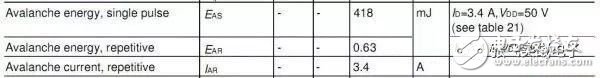
When a MOSFET enters avalanche mode, the voltage across the device is clamped, and the current flows through the parasitic transistor inside the MOSFET. If this current becomes too large, it can cause the MOSFET to fail.
Thus, it's essential to ensure that the avalanche energy and current stay within the rated limits specified in the datasheet.
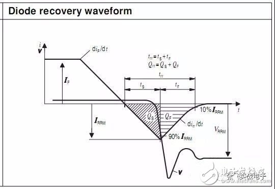
9. Body Diode Parameters
The body diode of a MOSFET has parameters such as forward voltage drop (VSD), reverse recovery time (trr), and reverse recovery charge (Qrr). Among these, trr and Qrr are particularly important because they affect switching losses. Smaller values are better for efficient operation.
Different power supply topologies have varying requirements for MOSFET parameters. Here are some general guidelines:
1). Flyback: Due to transformer leakage inductance, MOSFETs must have a high breakdown voltage. Typically, 600V or 800V devices are used depending on the design.
2). PFC and Hard-Switching Topologies: These require MOSFETs with low switching losses. Choosing MOSFETs with lower Qg helps reduce switching losses.
3). Soft-Switching Topologies (e.g., LLC, Phase-Shifted Full Bridge): These benefit from MOSFETs with fast-recovery body diodes to minimize reverse recovery losses.
4). Anti-Reverse and Oring Applications: In these cases, the MOSFET is always on, so conduction losses are the main concern. Rds(on) should be the primary selection criterion.
Feel free to share your thoughts and experiences in the comments below. Let's continue learning and improving together!
Single Axis Solar Tracker System
Single Axis Solar Tracker System price,Sun System Powered One Axis,One Axis Solar Tracker Single Axis,Mounting System Solar Tracker
Hebei Jinbiao Construction Materials Tech Corp., Ltd. , https://www.pvcarportsystem.com