In the user's home, a Skyworth 32E60HR LCD TV was brought in for repair. The TV shows a red power light but has a black screen. Pressing the touch power button doesn't work, and the remote control is also unresponsive. According to the user, the red light usually stays on, but when it turns off, the TV automatically powers on. This issue has occurred a few times before, but it usually resolves itself the next day.
After opening the back cover, I first checked the power supply voltages. The auxiliary power supply provided a normal +5V output, while the main power supply had no output for +12V, +24V, or +100V. There were no visible signs of leakage or burnout on the capacitors. [attach]448922[/attach]
Next, I tested the voltage regulator chips on the motherboard, which appeared to be functioning normally. My initial thought was that there might be an issue with the DDR not communicating with the main chip, or possibly a solder joint failure on the main chip itself. If the main chip wasn’t working, it wouldn’t send a power-on signal to the power supply, which would explain the lack of output. The user agreed to bring the motherboard, power board, and remote control for further testing at my place.
While testing the motherboard, I connected it to the power supply and heard a soft "click." That must have been the relay engaging! I looked at the power board and noticed a small relay at the end of the 220V line. It seemed to be controlled by the motherboard. To confirm, I disconnected all connections between the power board and the motherboard, then powered it up again. The relay didn’t engage this time. When I reconnected everything, I measured 2.9V on the PW-ON terminal. That’s definitely the boot signal from the motherboard! How could I have missed that earlier? [attach]448986[/attach]
Since the motherboard was sending a boot signal, it was working properly. However, the main power supply still had no output, so the fault must lie in the power board. But wait—could there be an issue with the motherboard’s firmware or software? I needed to double-check everything.
I checked the PCF voltage, which was normal. The switching transformer showed no obvious open or short circuits. The optocoupler also appeared to be in good condition, and the 12V and 24V rectification circuits were fine. However, during the 100V rectification check, I found that one side of the dual diode YG902C2 was broken. This is a 200V 10A 35ns Schottky diode. I tried replacing it with an MBRF20U200CT with similar specifications. After installation, the red light turned off, and the 100V output was restored. The other two voltages were also present. Great, it was fixed! But wait—the red light went out again. I checked the diode again, and the other two weren’t damaged. Could the MBRF20U200CT not be a proper replacement for YG902C2?
I searched online for genuine YG902C2 diodes, installed them, and checked the surrounding circuitry. Everything seemed okay. I powered it on again, and the red light came on—but then it went out again. What was going on? I examined the peripheral circuit
. After the 100V goes to the backlight constant current board, it also goes to the optocoupler control and the protection circuit. A diode rated for 200V must handle very high voltage or sharp pulses. I hadn’t connected the constant current board at all, so the other two circuits shouldn’t generate enough voltage to damage the diode. Why was it failing every time? [attach]449000[/attach]
Using a magnifying glass, I carefully inspected the pins of the switch transformer and noticed slight cracks. Some of the solder joints were loose. Ah, this must be the cause of the high-voltage pulse due to poor contact.
After re-soldering the connections, I installed the YG902C2 again. Powering it on, the red light turned off, and the voltages were stable. I repeated the test several times, and everything worked perfectly. I returned to the user's home, installed the TV, and it worked flawlessly.
This was my repair process. I’m not great at writing, but I hope this helps others understand how to approach similar issues. Thank you for reading!
All-in-one Energy Storage System
An energy storage system (ESS) is a device or set of devices used to store energy for later use. ESSs can store energy in various forms, including chemical, mechanical, thermal, and electrical energy. The stored energy can be used to power homes, buildings, or vehicles, or to supplement the power grid during periods of high demand.

ESSs are becoming increasingly important as renewable energy sources such as solar and wind power become more popular. These sources of energy are intermittent, meaning they only produce electricity when the sun is shining or the wind is blowing. ESSs can help to smooth out these fluctuations in energy production and make renewable energy more reliable and cost-effective.

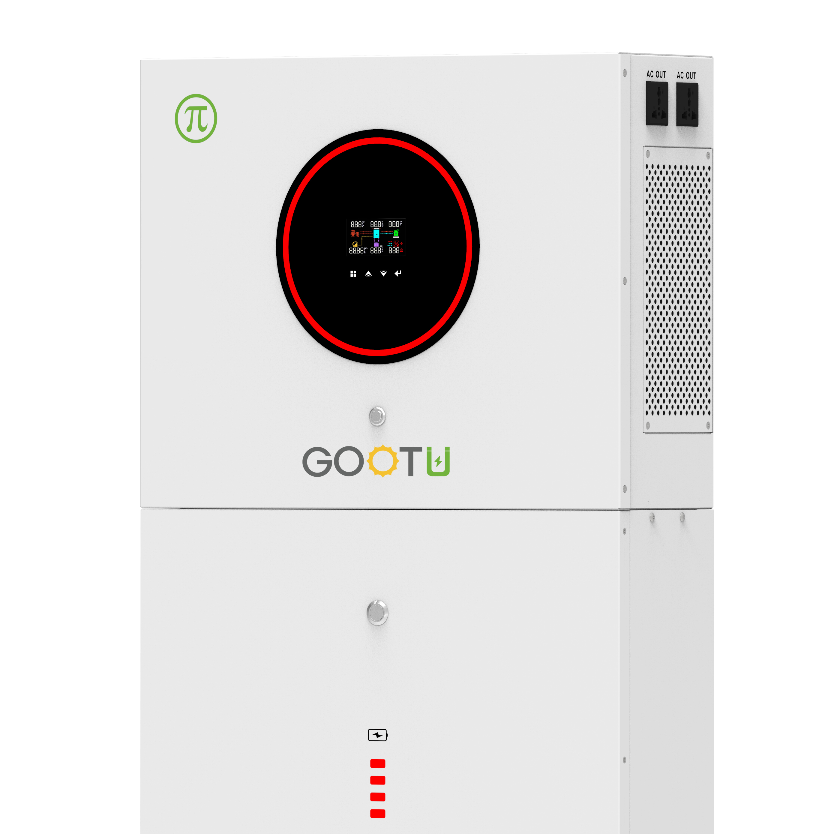
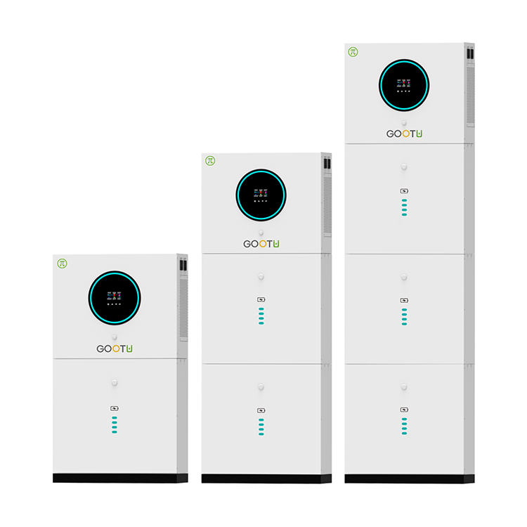
ESS is an integrated battery system that stores your solar energy for backup protection, so when the grid goes down your power stays on. Your system detects outages and automatically recharges with sunlight to keep your appliances running for days.GOOTU offers a modular, flexible design and can be easily customized to meet diverse customer needs.
Energy Storage System,Home Energy Storage System,Modular LiFePO4 Battery,Solar Energy Storage System,Renewable Energy Storage System
Shenzhen Jiesai Electric Co.,Ltd , https://www.gootuenergy.com