PID control is one of the most widely used and effective methods in automatic control systems. Many modern regulators are based on or inspired by the PID algorithm. In fact, it's safe to say that PID is the foundation of many advanced control strategies. But why has this technique remained so popular over the years?
The answer lies in its ability to address the core challenges of control theory: stability, response speed, and precision. By tuning the three key parameters—proportional (P), integral (I), and derivative (D)—engineers can optimize a system’s performance, ensuring it responds quickly while maintaining stability and minimizing errors.
The integral term helps eliminate steady-state error, making the system more accurate over time. The derivative term adds predictive capability, helping the system react to changes before they become significant. This combination makes PID an extremely powerful tool in various applications—from temperature control to robotics and beyond.
However, because each system behaves differently, the optimal PID settings can vary widely. This often poses a challenge for users, especially those new to control systems. To simplify the process, here are some general steps for tuning PID parameters:
1. Ensure the system uses negative feedback. For example, in a motor speed control system, if the input signal increases, the feedback should also increase, leading to a reduction in error. Always double-check your wiring and feedback configuration before starting.
2. Follow the general principles of PID tuning:
- Start with a low proportional gain and gradually increase it until oscillation occurs.
- Once the proportional gain is set, reduce the integral time constant (Ti) to improve accuracy without causing instability.
- Finally, add a small amount of derivative action (Td) to improve system responsiveness and dampen oscillations.
3. Use a step-by-step approach:
- Proportional Gain (P): Begin by setting Ti and Td to zero, then gradually increase P until the system starts to oscillate. Reduce it slightly to achieve stable operation and set P to about 60-70% of the critical value.
- Integral Time Constant (Ti): After setting P, slowly decrease Ti until oscillation appears, then increase it back to a stable level. Set Ti to around 150-180% of the measured value.
- Derivative Time Constant (Td): Typically, Td is set to a small value or even zero. If needed, use a similar method as for P and Ti, but keep it at around 30% of the oscillation point.
- Final Tuning: Once all parameters are set, test the system under different loads and adjust as necessary to meet performance requirements.
With proper tuning, the PID controller can provide excellent performance, making it an essential part of many modern control systems. Whether you're working on a simple temperature regulator or a complex industrial automation project, understanding how to effectively tune a PID loop is a valuable skill.
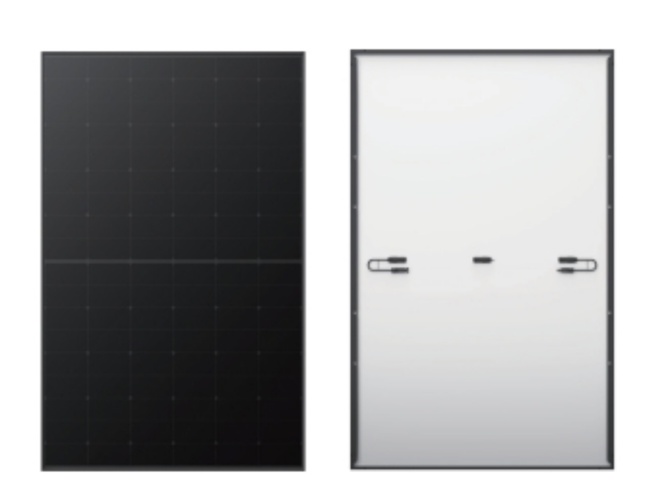
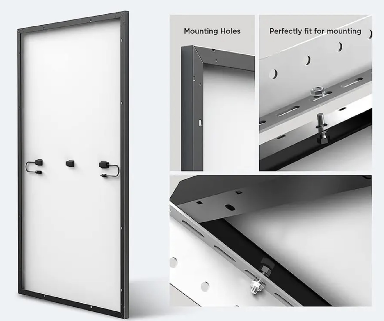
All black solar panels or black frame Solar Panel, power range around 400w to 460w which is higher solar panel efficiency the front black or front and back are both black.
All black solar panel data
| mono type | mono crystalline half cut cell |
| power range | 400watt to 460watt |
| dimensions | 1176*1134*30mm |
| type | monofacial type or bifacial type |
Product details and pic


All Black Solar Panel,Trina Solar Panel Vertex S,Mono Crystalline Pv Modules,Full Black Solar Panels 420Watt
PLIER(Suzhou) Photovoltaic Technology Co., Ltd. , https://www.pliersolar.com