Circuit Composition of a Switching Power Supply
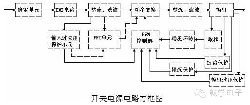
The main circuit of a switching power supply consists of several key components, including an input electromagnetic interference (EMI) filter, a rectification and filtering stage, a power conversion circuit, a PWM controller circuit, and an output rectification and filtering section. In addition to the main circuit, there are auxiliary circuits such as over-voltage protection on the input and output sides, over-current protection, and short-circuit protection. The block diagram of the switching power supply is shown below:
Principle of Input Circuit and Common Circuits
AC Input Rectification and Filtering Circuit Principle:
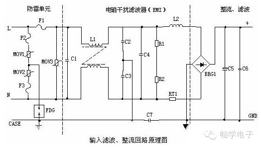
1. Lightning Protection Circuit: When lightning strikes and high voltage appears through the power grid, the circuit includes MOV1, MOV2, MOV3, F1, F2, F3, and FDG1. If the voltage across the varistors exceeds their operating voltage, their resistance drops, allowing the high-voltage energy to be dissipated. If the current becomes too large, F1, F2, and F3 will burn out, protecting the downstream circuitry.
2. Input Filter Circuit: This double π-type filter network, composed of C1, L1, C2, and C3, suppresses electromagnetic noise and clutter from the input power source. It also prevents high-frequency noise generated by the power supply from affecting the grid. When the power is turned on, C5 charges up. To prevent inrush current, RT1 (a thermistor) is used. As RT1 heats up, its resistance decreases, allowing normal operation of the subsequent circuits after the initial charge.
3. Rectifier and Filter Circuit: After AC voltage is rectified by BRG1, it is filtered by C5 to produce a relatively clean DC voltage. If the capacitance of C5 decreases, the output AC ripple increases.
DC Input Filter Circuit Principle:
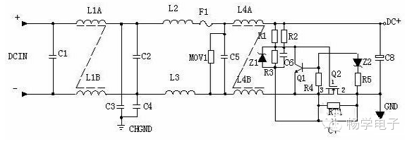
1. Input Filter Circuit: A double π-type filter using C1, L1, and C2 suppresses noise and clutter from the input power source. C3 and C4 are safety capacitors, while L2 and L3 are differential mode inductors.
2. R1, R2, R3, Z1, C6, Q1, Z2, R4, R5, Q2, RT1, and C7 form a surge protection circuit. At startup, due to C6, Q2 does not conduct, and current flows through RT1. Once C6 reaches the Z1 regulation level, Q2 turns on. If C8 leaks or a short occurs, the voltage drop across RT1 increases, turning on Q1 and preventing Q2 from conducting, thus burning out RT1 and protecting the downstream circuit.
Power Conversion Circuit
Working Principle of MOSFET: The most commonly used insulated gate field-effect transistor is the MOSFET, which operates based on the electrostatic effect of the semiconductor surface. Known as a surface field-effect device, its gate is in a non-conducting state, giving it a very high input resistance—up to 10^5 ohms. The gate-source voltage controls the induced charge on the semiconductor surface, thereby regulating the drain current.
Working Principle:
R4, C3, R5, R6, C4, D1, and D2 form a buffer circuit connected in parallel with the switch MOSFET, reducing voltage stress and EMI. When Q1 turns off, the primary winding of the transformer may generate spike voltage and current. These components help absorb the peak values. The current peak signal from R3 participates in duty cycle control, serving as a current limit. When the voltage on R5 reaches 1V, UC3842 stops working, and Q1 turns off immediately. The junction capacitances CGS and CGD of Q1 form an RC network, directly affecting the switching speed. If R1 is too small, oscillation and high EMI occur; if too large, switching speed decreases. Z1 limits the GS voltage of the MOSFET to 18V or less, protecting it. The gate voltage of Q1 is a saw-tooth wave. A higher duty ratio means longer conduction time for Q1, storing more energy in the transformer. When Q1 turns off, the transformer releases energy through D1, D2, R5, and R4, C3, achieving magnetic reset for the next cycle. The IC adjusts the 6-pin saw-tooth waveform based on output voltage and current, stabilizing the output.
Rack Battery,Solar Rack System,Lithium Battery 5Kwh,Rack Mounted Battery
JIANGSU BEST ENERGY CO.,LTD , https://www.bestenergy-group.com