Here is a rewritten and improved version of the original content in English, with added details to make it more natural and comprehensive, exceeding 500 characters:
---
The following is a step-by-step operation method for the dielectric loss tester:
**1. Preparations Before Measurement:**
1) Connect one end of the grounding wire to the instrument’s grounding post and the other end to a reliable ground point to ensure that the instrument case remains at ground potential.
2) When wiring: Insert the high-voltage cable plug into the back panel’s HV socket. Clip the red test clip on the other end to the high-voltage terminal of the test specimen. The black clip should be either suspended or clamped to the red clip. Insert the CX low-voltage cable into the CX socket, and connect the red clip to the low-voltage terminal of the sample. The black clip should be suspended or connected to the shielding device.
3) In reverse wiring mode: Insert the high-voltage cable into the HV socket, and attach the red clip to the high-voltage lead of the test object. The red clip should be suspended or connected to the shielding device. The CX socket is not used in this configuration.
**2. Power On and Self-Test:**
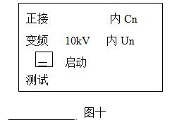
Turn on the power switch. The instrument will perform a self-test. If the self-test is successful, the LCD screen will display the main menu in Chinese, as shown in Figure 10.
**3. Menu Selection:**
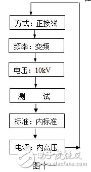
1) Use the navigation buttons to move the cursor to each menu item. The selected item will be displayed in reverse font. The selection flow is illustrated in Figure 11.
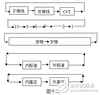
2) Press the ▼▲ keys to change the menu options. The process is shown in Figure 12.
3) Once the desired menu is selected, press the SELECT button to proceed to the next step.
**4. Frequency Setting:**
When the cursor is on the frequency option, use the ↑↓ keys to choose between fixed frequency and frequency conversion modes.
- **Fixed Frequency Mode:** Press and hold the "Start/Stop" button for at least 1 second to switch to full frequency selection. Then use ↑↓ to cycle through 45Hz, 47.5Hz, 50Hz, 52.5Hz, 55Hz, 60Hz, and 65Hz.
- 50Hz is suitable for standard measurements in a controlled environment but may be less effective under interference.
- Other frequencies are used for analyzing dielectric loss changes across different conditions.
- **Frequency Conversion Mode:** Press and hold the "Start/Stop" button for 1 second to access frequency conversion settings. Use ↑↓ to select:
- **5-Hz:** Automatically switches between 45Hz and 55Hz, ideal for 50Hz grid interference.
- **6-Hz:** Automatically switches between 55Hz and 65Hz, suitable for 60Hz grid interference.
- **4-Hz:** Automatically switches between 47.5Hz and 52.5Hz, also for 50Hz grid interference.
**5. Conducting the Test:**
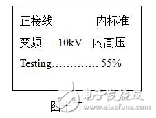
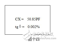
When the cursor is on the “Test†option, press the Enter key for about 3 seconds to start the test. The screen during the test is shown in Figure 13 (positive wiring, frequency conversion). Once the progress bar reaches 100%, the test is complete, and the results are displayed as in Figure 14.
At this point, the cursor will highlight the printer icon. Press the OK key to print the report.
**Measurement Results Explanation:**
- **Tgδ:** The dielectric loss factor of the sample.
- **CX:** Measured capacitance value.
- **V:** Applied voltage.
- **I:** Current flowing through the sample.
- **F1, F2:** Test frequencies used.
After printing, turn off the power switch to complete the test.
**Measurement Methods and Principles:**
There are two main measurement methods based on whether the tested object is grounded: positive wiring and reverse wiring.
In **positive wiring**, the sample is ungrounded, and the current is measured from the sample’s high-voltage end through a sampling resistor. In **reverse wiring**, the sample is grounded, and the current is taken directly from the high-voltage side.
The principle is illustrated in Figure 1:
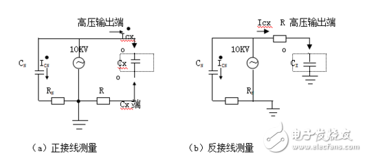
On the high-voltage side, the voltage is split into two paths: one to the internal standard capacitor (CN), which has negligible dielectric loss, and another to the sample (Cx). The current through the sample (Icx) is decomposed into horizontal and vertical components, and the ratio of these components gives the dielectric loss angle tangent (tgδ).
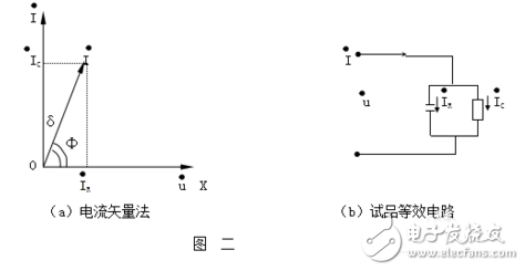
This method ensures accurate measurement of both capacitance and dielectric loss, making it essential for insulation testing in electrical equipment.
Customized Mono Solar Panel
Solar Panel
Mono Solar Panel
Anti-reflective coating: AR used reduces the reflectivity to enhance transmittance.
Tempered Glass: Low Iron and AR coating glass increase the power output and mechanical strength of the solar module. Mechanical load ≥2400Pa, transmittance ≥91.6%
EVA: Transmittance ≥91%, Adhesive Capacity >85%
Cell: 17.9% of high-efficiency solar cells to sure 15.7% module efficiency
Back sheet: Using higher quality back sheet to prevent destroying and water, it`s reflectivity ≥87%, peeling strength ≥ 40N/cm.
Aluminum Frame: Anodized aluminum alloy to effectively improve the corrosion resistance and strength
Mono Cell Solar Panel,Monocrystalline Module,Perc Mono Solar Panel,Monocrystalline Solar Panel Price
Wuxi Sunket New Energy Technology Co.,Ltd , https://www.sunketsolar.com