 Capacitor step-down circuit is a common small current power circuit. Because of its small size, low cost and relatively constant current, it is also commonly used in LED drive circuits.
Capacitor step-down circuit is a common small current power circuit. Because of its small size, low cost and relatively constant current, it is also commonly used in LED drive circuits.
Figure 1 shows an actual LED driver circuit with capacitor step-down: Please note that most of the application circuits do not have a varistor or a transient voltage suppression transistor connected. It is recommended to connect the varistor or transient voltage suppression transistor. At the moment of sudden voltage change (such as lightning, large power equipment startup, etc.), the abrupt current is effectively discharged, thereby protecting the secondary level and other transistors, and their response time is generally in the order of micro milliseconds.
Circuit working principle:
Capacitor C1 functions as buck and current limit: As we all know, the characteristics of the capacitor are AC and DC. When the capacitor is connected to the AC circuit, the capacitance calculation formula is:
XC = 1/2Ï€f C
In the formula, XC represents the capacitive reactance of the capacitor, f represents the frequency of the input AC power source, and C represents the capacity of the step-down capacitor.
The current calculation formula flowing through the capacitor step-down circuit is:
I = U/XC
Where I represents the current flowing through the capacitor, U represents the supply voltage, and XC represents the capacitive reactance of the capacitor.
In the 220V, 50Hz AC circuit, when the load voltage is much less than 220V, the relationship between current and capacitance is:
I = 69C where the unit of capacitance is uF and the unit of current is mA
The following table compares the theoretical current with the actual measured current in an AC circuit of 220V and 50Hz.
The resistor R1 is a bleeder resistor, and its function is: when the sine wave is cut off at the maximum peak time, the residual charge on the capacitor C1 cannot be released, and it will exist for a long time. If the human body touches the metal portion of the C1 during maintenance, there is a strong The possibility of electric shock, and the presence of the resistor R1, can release the remaining charge, thereby ensuring the safety of people and machines. The resistance of the bleeder resistor is related to the size of the capacitor. The larger the capacity of the capacitor, the more residual charge, and the bleeder resistor should be smaller. The empirical data is as follows, for design reference:
The role of D1 ~ D4 is rectification, which is used to rectify the alternating current into a pulsating DC voltage.
The function of C2 and C3 is filtering, and its function is to filter the rectified pulsating DC voltage into a smooth DC voltage.
The function of the varistor (or transient voltage suppression transistor) is to discharge the instantaneous high voltage of the pulse in the input power supply to the ground, thereby protecting the LED from instantaneous high voltage breakdown.
The number of LEDs connected in series depends on their forward conduction voltage (Vf), and can reach up to 80 in a 220V AC circuit.
Component selection: The capacitor's withstand voltage is generally required to be greater than the peak value of the input power supply voltage. In 220V, 50Hz AC circuits, you can choose a polyester capacitor or paper dielectric capacitor with a withstand voltage of 400V or more.
D1 ~ D4 can choose IN4007.
The withstand voltage of the filter capacitors C2 and C3 depends on the load voltage, and is generally 1.2 times the load voltage. Its capacitance depends on the magnitude of the load current.
The following circuit diagrams are other forms of capacitor buck driver circuits for design reference:

In the circuit of Figure 2, the thyristor SCR and R3 form a protection circuit. When the current flowing through the LED is greater than the set value, the SCR is turned on a certain angle, thereby shunting the circuit current, so that the LED operates in a constant current state. This prevents the LED from being damaged by an instantaneous high voltage.

In the circuit of Figure 3, C1, R1, varistor, L1, R2 form the primary filter circuit of the power supply, which can filter the input high voltage, C2, R2 form the step-down circuit, C3, C4, L2, and varistor The rectified filter circuit. This circuit uses a double filter circuit to effectively protect the LED from damage caused by transient high voltage breakdown.

Figure 4 is the simplest capacitor step-down application circuit. The circuit uses two anti-parallel LEDs to rectify the decompressed AC voltage. It can be widely used in night light, button indicators, and position indicators that are not required. Etc.
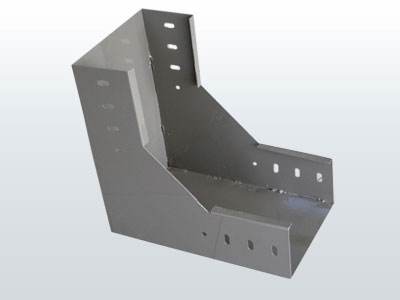
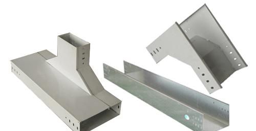
Cable Tray bend is one kind of cable tray accessories.It can connect cable trays when you need them to change directions in vertical
or horizontal.And we also supply Cable Tray Bends when you need them to connect cable trays with different diameters.With these bends ,your cable tray
can fix different indoor structures.
materials.


Cable Tray Bends,Soild Waterproof Cable Tray,Ventilated Trough Cable Tray,Horizontal Cable Tray
Jiangsu Loncin Electrical Equipment Co.,Ltd , https://www.loncincabletray.com