So use the state machine to design the deletion of the SKP pair in USB3.0, as shown below. When the SKP window is invalid, the state is in idle; when the SKP window is valid and the threshold is triggered, the state enters the mask state; when the SKP window is valid, the mask state continues until the delete threshold flag is invalid; when the SKP window is invalid, Or if the delete threshold flag is invalid and the number of masked SKPs is an even number, the state returns to the idle state.
This article refers to the address: http://
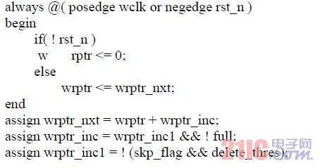
The pointer mask verilog code is as follows.
3.2 Adding SKP in USB3.0
SKP add modules include breakpoint save, write pointer jump and handshake, read pointer generation and output control module SKP addition occurs when the read clock is faster than the write clock. Under normal circumstances, the elastic buffer read operation is no different from the normal FIFO. .

Figure 9 SKP add structure
3.2.1 Breakpoint save
In the normal half full mode, the read and write pointers differ by 8 clocks. Therefore, in the event of a write pointer, it takes about 8 clocks to pass to the read pointer. When the SKP window appears, if the threshold flag is added, the read pointer will take 8 clocks to add SKP.
For adding SKP pairs, how can I read the pointer to know how much to add? Therefore the read pointer needs to write the pointer to boot. In the design, breakpoint save and handshake are used to solve. When the SKP window appears and the threshold value is added, the write pointer calculates the number of valid data in the FIFO at this time, and determines the next pointer point pointed to by wrptr_nxt according to the difference between the number of valid data in the FIFO and 8 It is the write pointer jump. And in the write clock domain, the current write pointer and the pointer point pointed to by the next one are saved. In the elastic buffer design, the read pointer always lags behind the write pointer.
Figure 10 Write pointer save breakpoint
3.2.2 Handshake
The write pointer jumps when the SKP window and the SKP add threshold are triggered, and the breakpoint is saved, but this is only in the write clock domain. Since the read pointer is later than the write pointer, a handshake is used to inform the read clock domain when to add SKP. As shown in the figure below, when the SKP window appears and the threshold is triggered, the elastic buffer saves the breakpoint and initiates a request (req) to the read clock domain. The request continues until the read pointer reads the start address of the breakpoint (start_rptr). At this time, the read pointer reads the start address of the breakpoint and sends a receipt (ack) to the write clock. When the write clock domain receives the ack signal of the read clock domain, req is cancelled. The read clock domain automatically cancels the ack signal once it has read the cutoff address (end_ptr). The SKP pair is added during the ack process of the entire read clock domain.

Figure 11 handshake
3.2.3 Output Control
In the process of elastic buffer FIFO read/write control, the write precedes the read. First, the delay is written to the specified requirement. At this time, the write valid read is invalid (defined as W1R0). When the specified threshold is reached, the read and write are valid at the same time (W1R1). Wait until the end of the write, that is, a packet is received, but the read does not end (W0R1) until the read is empty, that is, all data has been synchronized to the local (W0R0) to indicate the end of the task. This process control is to maintain the integrity of this data.
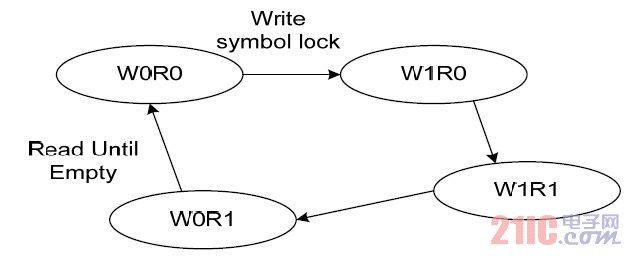
Figure 12 read and write process control
The USB protocol clearly specifies that the SKP pair is 2 consecutive SKP symbols. According to the 8b10b principle, the run of two consecutive SKP pairs is reversed, and the addition of SKP pairs is in accordance with the rules of 8b10b3.
It is required to add an EDB character when the elastic buffer underflows, and use the underflow flag explicitly. As shown in the figure below, between rx-g and rx-h, the underflow is caused by the read being faster than the write. Therefore, it is necessary to add an EDB character and enable a clock underflow and set the state.
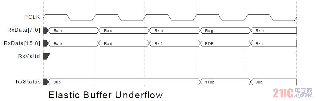
Figure 13 elastic buffer underflow
PIPE 3.0 requires that when the elastic buffer overflows, a data is discarded and the state is set. As shown in the following figure rx-f, rx-g and rx-h, rx-g is discarded due to overflow, and the state is set.
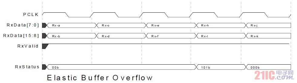
Figure 14 elastic buffer overflow
5. Summary
In this paper, by analyzing the role and mechanism of elastic buffer, the asynchronous buffer FIFO is used to design the elastic buffer. According to the requirements of USB3.0 protocol, methods such as breakpoint save, pointer jump and handshake, pointer masking, etc. are proposed to design elastic buffer. This design fully considers the requirements and practical needs of the PIPE 3.0 standard, and is applied in engineering to achieve the purpose of elastic buffer compensation clock.
1 Introduction
The elastic buffer is proposed by Maurice Karnaugh in transmitting PCM signals over the telephone network. Then, in many different applications, elastic buffering technology was used to synchronize data. Many protocols such as USB, PCIE, Ethernet, etc.
USB 3.0 is a high speed, serial, source synchronous data transfer protocol. However, the data has a large deviation from the original data through the transmission line. This paper analyzes the elastic buffer mechanism from the perspective of USB3.0, explains the difference from other designs, and adopts the design method of pointer control and handshake.
2. Elastic buffering
2.1 USB3.0 elastic buffer scope
In USB3.0, data transmission uses double simplex, so the physical layer is designed to receive and transmit two sets of differential pair transmission parts. A transmission line is a carrier that carries data transmission. So how to correctly receive data from the transmission line and synchronize it to the internal clock domain of the system is very critical.
The physical layer receiving part structure diagram specified in USB 3.0 is as follows, which includes differential reception, clock data recovery, serial-to-parallel conversion, and 8B10B decoding.
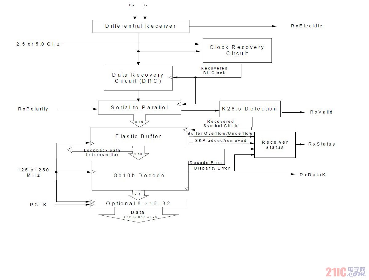
Figure 1 USB3.0 physical layer receiving part of the structure
The entire data flows from top to bottom, the differential input is differentially received, the clock is extracted from the differential signal, and the recovered clock is used to recover the data (CDR). The recovered data is serially converted into a 10-bit bit-width parallel data 1 in the receive clock domain, and the USB 3.0 packet start identifier (K28.5) is detected. Once the start identifier K28.5 is detected, the symbol lock is enabled until the end symbol is detected, and the end symbol is valid.
The elastic buffer receives data from the serial-to-parallel conversion, and all received data and control operate in the receive clock. Therefore, the elastic buffer synchronizes the data and control to the system clock. The data is passed down to the 8B10B decoding module and then passed to the system.
2.2 Elastic buffer capacity
In USB 3.0, the protocol specifies a clock accuracy of -5300 ppm to 300 ppm. The symbol clock frequency is 2ns or 2000ps. In the worst case, one SKP is added or deleted for every 178 symbols, that is, one SKP Order Sets is added or deleted for every 356 symbols. The maximum length of the USB3.0 package is 1052 bytes, so in the worst case, up to 8 SKP or 4 SKP pairs can be added or deleted, so the elastic buffer must buffer at least 8 SKPs. The USB 3.0 protocol specifies that each SKP order set is 2 consecutive SKP symbols. Therefore, before the 10B8B decoding, the running disparity of the SKP order set should be complementary.
It is calculated that the buffer capacity of the elastic buffer is 8. This design uses the normal half full mode to design the elastic buffer, so the elastic buffer capacity is 16, under normal circumstances there should be 8 data inside, the remaining 8 are buffer space, so called often half full . The normal half-full mode first needs to write 8 symbols to the buffer to half full, then the read enable can be effective, so there is about 8 clock delays. Normal half full mode can only add or delete SKP pairs if SKP pairs appear in the symbol queue. The figure below shows the regular half-full input and output timing diagram.

Figure 2 often half full input and output timing
As can be seen from the above figure, rx_valid_out is valid after about 8 clock edges of rx_valid_in; and invalid is later than rx_valid_out by about 0 to 16 clock edges (depending on the difference in clock precision). Therefore, it usually takes 8 clock delays to output data.
2.3 elastic buffer mechanism
The elastic buffer is essentially an asynchronous FIFO that is controlled by both reading and writing. The normal half full FIFO has a depth of 16, and must first write 8 valid data and maintain it in a half full state. Therefore, under normal circumstances, the FIFO is always at or near the half full state. When the read/write clock is as fast as possible, there are 8 valid data in the FIFO.
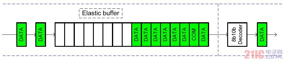
Figure 3 often half full read and write equivalent rate
When the read clock is faster than the write clock, more data is read than the written data. The normal half full mode may cause the amount of data in the FIFO to be less than 8, and may even be read out. As shown in the figure below, when the SKP window appears, the valid data in the FIFO is 4, which is 4 less than the normal state. So at this point, the elastic buffer should add 4 SKPs to keep the FIFO half full to adjust the clock. At this time, the read pointer jumps forward by 4 intervals, and when the read pointer reads the jump section, the SKP addition is completed.
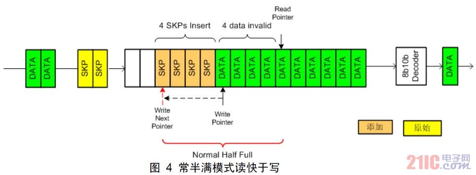
Figure 4 often half full mode read faster than write
When the read clock is slower than the write clock, more data is written than the read data. The normally half full mode may cause the number of data in the FIFO to be more than 8, and may even be filled. As shown in the figure below, when the SKP window appears, the valid data in the FIFO is 10, which is more than the normal state. 2. Therefore, at this time, the elastic buffer should delete 2 SKPs so that the FIFO is half full to adjust the clock. At this point, the write pointer should be suspended for 2 clock cycles to complete the SKP deletion.
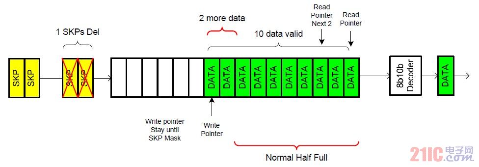
Figure 5 is often half full and faster than reading
3. Elastic buffer structure
The structural design of the elastic buffer in the normally half full mode can be divided into receiving clock domain control, system clock domain control, threshold detection and synchronization. Receive clock domain control includes write control and write pointer control. System clock domain control includes read control and read pointer control. Threshold detection and synchronization includes synchronization between the SKP add-off threshold and the clock domain.

Figure 6 Normal half full mode elastic buffer structure
3.1 USB3.0 SKP deletion
Write enable may only be effective when the symbol lock of the receive clock domain is active. It can always be written that the FIFO is in a half full state, at which time the FIFO is in a critical state, and the difference in read and write rates will result in triggering of different thresholds. The figure below is the deletion of the SKP pair.

Figure 7 SKP pair delete
The detecting unit is used to detect whether the data entering the FIFO is SKP, and functions to mark the SKP window, and provides a window for the deletion of the SKP. The threshold monitoring unit constantly monitors the amount of valid data in the FIFO. If the number is greater than the delete threshold (10 valid data in the FIFO), and the SKP window is valid, then the elastic buffer pauses the pointer and masks the SKP pair to achieve the purpose of deleting the SKP pair. However, SKPs in USB 3.0 are all in pairs, so you should pay attention to parity when deleting SKP pairs.
The Preformed Helical Fitting is mainly used in wire,ground wire installed hardware. According to the performance of the structure can be divided into:
1.Preformed Suspension Clamp:used to hang the conductors and ground wires on the perch.
2.Preformed Strain Clamp:bears all tension,connect the wire and ground wire on the tension tower
3.Splicing Fitting:used to two ends of conductor,instead of the conventional hydraulic compression splicing sleeve and pressure pipe.
4.portective fitting:used to protect the conductors and insulators,generally divided into armor rod,repair sleeve,vibration damper.
Material generally adopt aluminum alloy,hot-dip galvanized steel. Fasteners are hot-dip galvanized steel.

Preformed Helical Fitting
Preformed Helical Fitting,Preformed Splicing Fitting,Preformed Protective Fitting,Preformed Line Fitting
Jiangsu Chuandu Electrical Technology Co.,Ltd. , http://www.cdepf.com