0 Preface
Due to the rapid development of microelectronics and digital circuits and the substantial increase in the speed and performance of weapon systems, the system also proposes indicators such as frequency range, resolution, frequency conversion time, and signal form diversification in radar, navigation, and electronic measurement fields. Higher requirements. DDS (Direct Digital Synthesis) technology with its extremely high frequency resolution (on the order of a few microhertz), extremely short frequency conversion time (several nanoseconds), wide relative bandwidth, continuous output phase, and arbitrary waveform output capability Other advantages have been widely used in digital modulation circuits.
This paper describes the application design for a digital modulation unit in a tracking radar. The scheme uses a combination of DDS and CPLD, and is loaded by software to generate various signals, thereby forming a flexible multi-frequency, multi-mode digital modulator. At the same time, the circuit is also digital, small in size, and can be programmed online.
1 Digital Modulation Unit Design
1.1 Working principle
A schematic block diagram of a radar digital modulation unit based on a DDS chip and a CPLD is shown in FIG. The radar digital modulation unit is designed with the AD9857 as the core. The AD9857 is a high-performance general-purpose quadrature digital upconverter from AD. It integrates a half-band filter, CIC filter, anti-SINC filter, and high-speed number. The analog converter, whose core is a phase continuous direct digital synthesizer (DDS). In the quadrature modulation mode, the DDS can accept the frequency control word input by the serial port, and the quadrature local oscillator signal generated by the control is multiplied by the baseband I and Q signals, and then added to generate a quadrature modulated signal, and finally The 14-bit digital-to-analog converter becomes an analog signal output, enabling digital modulation of the signal. In this circuit, the CPLD first writes various control words into the internal register through the serial port of the AD9857 to realize the initialization of the AD9857. The serial clock uses an external 10MHz crystal oscillator. After the initialization is completed, the PDCLK signal output by the AD9857 can be used as the synchronization of the I and Q data. clock. The I and Q data are stored in the EPROM. The address generation unit in the CPLD uses the PDCLK signal as a reference to generate the corresponding address, and sends the I and Q data in the EPROM to the AD9857.
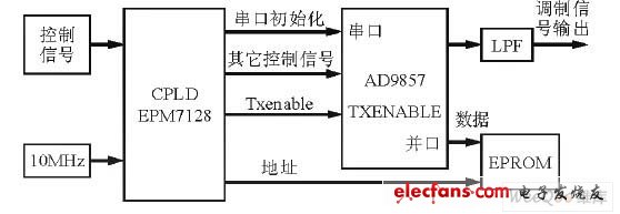
Figure 1 Digital modulation unit block diagram
1.2 Serial Port Initialization
When the system is powered up, the CPLD can initialize the AD9857. Initialization can be realized by writing various control words to the internal registers through the serial port of AD9857. The serial clock uses an external 10MHz crystal oscillator. The serial port connection relationship is shown in Figure 2.
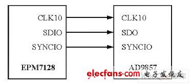
Figure 2 serial port connection circuit
The writing software can use MAX+PLUS II as the platform, adopt modular method, and combine VHDL and principle input method to complete. The schematic symbol of the initialization module is shown in Figure 3.
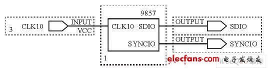
Figure 3 Initialize the simulation symbol
Figure 4 shows the MAX+PLUS II simulation results for the initialization section.
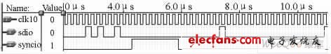
Figure 4 Initialization simulation results
1.3 Parallel connection of modulated data
The parallel interface of AD9857 is mainly composed of 14-bit data lines D0~D13, clock signal PDCLK, and transmission enable Txenable.
In order to make the circuit have multiple modulation modes, the modulation mode data can be stored in EPROM CY7C291, A0~A13 are data addresses, and A14~A15 are modulation mode selection. The lower 14-bit data D0~D13 of CY7C291 is connected to the parallel data port of AD9857. The clock signal is provided by the PDCLK pin of AD9857. Its parallel connection relationship is shown in Figure 5.
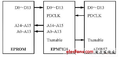
Figure 5 parallel data port connection circuit
2 Modulation signal generation
2.1 Generation of phase coded modulated signals
Usually any modulated signal can be expressed as:
![]()
If I (n) = cosФ (n), Q (n) = - sinΦ (n), then I (n), Q (n) are the I and Q baseband data corresponding to the modulated signal. The tracking radar uses a 0, π phase-encoded signal, in equation (1): If I (n) =0, Q (n) = FFH (lower 8 bits are all 1), then: S (n) = sin ( Ω0n); If I (n) = FFH (lower 8 bits are all 1), Q (n) =0, then S (n) = cos (ω0n).
A sine wave of the same frequency with a phase difference of π is generated, and I and Q data corresponding to the 0 and π phase modulation signals are obtained. Since the I and Q signals in the parallel data stream are alternately transmitted, the I and Q data stored in the EPROM are as shown in FIG. 6.
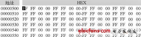
Figure 6 0, π phase modulation signal I, Q data
In order to quickly control the frequency, different frequency control words can be stored in different profiles in the AD9857, and then the switching of the PS1 and PS0 pins can be controlled by an external signal, thereby realizing the rapid generation of signals of different center frequencies.
2.2 Nonlinear frequency modulation signal
The baseband I and Q data used in the nonlinear frequency modulation mode (the calculation method is similar to 3.1.2) is shown in Fig. 7.
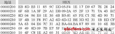
Figure 7 Nonlinear FM signal I, Q data
The Txenable signal is a pulse signal with a duty cycle of 10% and can be used as an input signal for external pulse control. The spectrum of the generated nonlinear frequency modulated signal is as shown in FIG. The non-linear FM signal in the figure has a center frequency of 30 MHz and a bandwidth of 1.5 MHz.
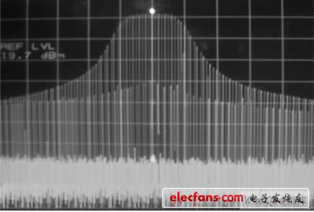
Figure 8 Spectrogram of nonlinear FM signal
3 Conclusion
Through the test data, the digital modulation system described in this paper can generate various forms of modulated signals, and can switch between pulses, and the volume is small, which is convenient for system integration. The system has been applied to a tracking radar system, and its use proves that its design can meet the requirements of the whole machine and the effect is good.
Ac Linear Actuator,Miniature Linear Actuators,24V Linear Actuator,Mini Linear Actuator
Changzhou Sherry International Trading Co., Ltd. , https://www.sherry-motor.com