Insulated Gate Bipolar Transistor (IGBT) is a minority carrier power component with high input impedance and high bipolar current capability. These features make it suitable for a wide range of power electronics, especially motor drives and uninterruptible power systems ( UPS), renewable energy systems, welding machines, induction cookers, and other inverter applications that support high current and high voltage.
In addition, short-circuit resistance is also an important feature of IGBTs for all types of inverters. In a UPS or motor driven by an inverter, the IGBT will be damaged when a motor failure, an output short circuit, or an input of a voltage shoot through occurs during startup. Under these conditions, the current through the IGBT will increase rapidly until saturation, and the IGBT should be able to withstand this pressure before fault detection and protection are enabled.
Three-level topology inverter ignites 650 volt IGBT requirements
From the perspective of inverter design, the three-level Neutral-point-clamped topology is accelerating and spreading to low- and medium-power power converters to provide higher output voltage spectrum performance. This reduces filter size and reduces cost while increasing the switching frequency without generating excessive switching losses.
In the three-stage NPC topology, because the DC link voltage cannot be well balanced, a higher blocking voltage is required in this topology. For this, an IGBT supporting a 650 volt breakdown voltage can be effective. To meet this design demand, market penetration is gradually rising. However, usually the higher breakdown voltage will increase the Vce(sat), which will reduce the performance of the inverter application. Therefore, how to make the switching and conduction loss of the 650 volt IGBT maintain the same level as the traditional 600 volt IGBT solution. Chip makers and system manufacturers are undoubtedly the most important direction.
The inter-electrode saturation voltage (Vce(sat)) and switching efficiency of the IGBT are mutually increasing and decreasing. The main cause is the Vce(sat) compensation value added by the high breakdown voltage design, which may cause the system to generate large switching loss. Finding the best design balance point in the growth and descent curve will be the key to optimizing the performance of 650 volt IGBTs.
In order to meet the above requirements, the new Field Stop Trench IGBT has emerged with a 650 volt breakdown voltage, very low Vce (sat) and short circuit resistance, and the performance has been verified by system level evaluation.
Field-cut trench IGBTs combine high voltage and low Vce(sat) benefits
The field-cut trench technology uses a trench gate structure and a highly doped n+ buffer layer that is responsive to penetration characteristics. Due to the aforementioned characteristics, the new IGBT technology achieves a higher Cell density, which has a very low on-state voltage drop for a specific silicon area; overall, the current density can be more than double that of the old field cut-off planar solution.
Figure 1 shows a comparison of the Vce(sat) and switching loss characteristics of a new 75 amp (A), 650 volt field-cut trench IGBT, and a 75 amp, 600 volt old field-cut planar IGBT, the former at 25 ° C, 75 At ampere, 1.56 volts Vce(sat) can be achieved, and under the same conditions, the latter is 1.9 volts.
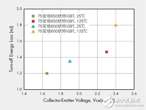
Figure 1 Comparison of the characteristics of the new 650 volt IGBT and the old 600 volt IGBT
In general, higher IGBT blocking voltage and smaller size will increase Vce(sat), and the field-cut trench technology can further reduce the chip area and significantly reduce the breakdown voltage to 650 volts. This situation is improved; therefore, low Vce(sat) is a major advantage of the novel field-cut trench IGBTs, while also reducing turn-off energy losses at each switching cycle.
As the voltage characteristics of IGBTs improve, the system plant will be able to create inverters with higher conversion efficiency to meet market demands. It is worth noting that even if the silicon area is reduced, the new field-cut trench IGBT can provide 5 microsecond (μs) short-circuit time before the fault due to thermal dissipation, and the old IGBT does not support this function; The field-cut trench IGBT has a low off-state leakage current and supports a maximum junction temperature of 175 °C.
![]() Great victory over traditional design 650 volts IGBT performance
Great victory over traditional design 650 volts IGBT performance
As for the new 650 volt field-cut trench IGBT, compared to components using similar schemes, the conditions are Tj=25°C, Ic=80 amps, Vce=400 volts, Vge=15 volts, and Rg=5 ohms (Ω). In the switching test, the 650 volt IGBT showed a switching-off energy loss of 183 microjoules (μJ) and a 600 volt IGBT switching loss of 231 microjoules.
The evaluation project also includes a co-packaged diode (Diode) reverse recovery characteristic with test conditions of If=40 amps, Tj=125°C, Vr=400 volts and di/dt=500 amps/microsecond under the above conditions. The Qrr of the field-cut trench IGBT is 1.17 microcoulomb (μC), which is much lower than the competitor's IGBT of 3.98 microcoulomb.
In the bridge topology, the lower Qrr value can reduce the IGBT turn-on loss of the single-pin; the switching efficiency can be verified by the commercial 5.5kW parallel solar inverter, which has the front-end boost stage and In the bipolar control full-bridge inverter phase, the switching frequency of both phases is 19 kHz. In the initial design, the boost phase remains the same, but 650 volt IGBTs and 600 volt IGBTs are used in the full bridge inverter stage.
Figure 2 shows the inverter's introduction of two IGBT efficiency test results. The 650 volt solution has a EURO and CEC weighted efficiency of 94.37% and 95.08%, respectively, while the 600 volt scheme is 93.67% and 94.37%, respectively, due to the new field stop trench. The IGBT has excellent switching efficiency and therefore shows higher efficiency.
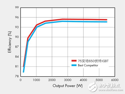
Figure 2 Comparison of the efficiency of introducing new and old IGBTs into the inverter
Figure 3 shows the new 50 amp field-stop trench IGBT and the comparison of the old-class products. The new scheme shows excellent growth and depletion conditions at 10 amps and 20 amps. These two currents are the actual operation for most applications. Current.
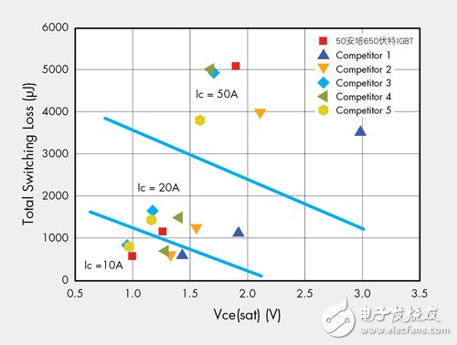
Figure 3 Efficiency of the inverter using different IGBTs at 10 amps and 20 amps
Based on the aforementioned comparison results, the power loss in the system can be further estimated. Assume that the target system is a 3kW rated mixed full-bridge inverter with two low-end IGBTs built in line frequency switching, and two high-end IGBTs to switch at 17kHz. Figure 4 is a summary of its power loss estimation. To verify the power loss estimate, a 50 amp/650 volt IGBT can be used separately, and the power loss is compared to a similar IGBT No. 3.
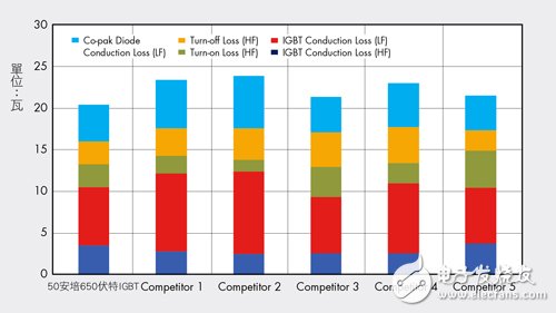
Figure 4 Power loss estimation for new IGBTs and other competing solutions
As shown in Figure 5, when the 3kW system is fully loaded, the power consumption of the No. 3 IGBT and the 50A/650V IGBT is quite close. This situation is completely in line with the estimation. In addition, the efficiency fault will gradually increase as the load decreases. It also meets the efficiency variation of Figure 3. At low current levels, the 50 amp/650 volt IGBT performs best.
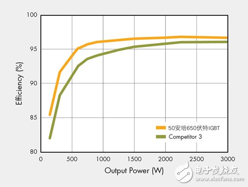
Figure 5 Comparison of efficiency of different IGBTs for mixed full-bridge inverters
The new 650 volt field-stop trench IGBT has been introduced recently, and its performance has been evaluated by the system factory. Compared with the old IGBT, the new scheme provides better DC and AC (AC) characteristics, and is resistant to short-circuit time and leakage current. Problems have been improved to support more efficient and reliable converter systems.
All auto filters are designed to prevent harmful debris from entering any parts where air and fluid flows, including your engine, radiator, fuel lines and more. Once a filter is no longer performing its intended function, decreased performance-even engine damage-can result.
When your air filter is dirty, your engine is forced to work harder, resulting in poor fuel economy, higher emissions and, possibly, a loss of engine power. In turn, as a worst-case scenario, a clogged Cabin Air Filter can lead to under-performance of the A/C system, causing weak air flow from the cabin vents. It can also lead to unwanted, unfiltered air in the cabin. As for a mucked-up fuel filter, that`ll land you with a weakened fuel supply to injectors, a reduction in engine power, poor acceleration and lousy fuel economy-not to mention a potential breakdown.
They protect vital car parts by keeping harmful debris at bay so your car runs right. Filters also ensure your car runs more efficiently. The cleaner your filter, the more it allows for the maximum flow of air or fluid through the system. Like a clogged drain, a dirty filter starves the system of the vital air or fluid and makes each system it protects work harder to do its job. Once filters are dirtied, they should be replaced.
it`s recommended that you get your filters replaced every 12 months or 12,000 miles, but check your owner`s manual for specifics about your vehicle`s filter replacement schedules.
Automotive Filter,Car Air Filter,Car Cabin Air Filter, Car Oil Filter
Donguan Bronco Filter Co., Ltd , https://www.broncofilter-cn.com