introduction
LED-based signage and matrix displays bring more functionality and stunning visual effects to growing indoor and outdoor applications. The latest developments in LED technology make it difficult to tell whether you are seeing a still picture of a high-quality display or a traditional printing or drawing billboard. This article will detail the basic technical principles of LED display systems and the design issues they need to consider when designing discrete LED bulb arrays.
LED driver base
First, we have to compare different LED driver circuits to determine the best solution.
Connecting voltage source
It is well known that an LED lamp (or diode) begins to conduct when it has a sufficient forward voltage (VF). The forward current usually glows when turned on. Based on this basic knowledge, the first option in Figure 1a can be derived, but this does not work. Because the LED current is an exponential function of its voltage bias (Equation 1), the light intensity of the LED is very sensitive to this voltage. In most cases, high current conditions typically turn an otherwise long-life LED into an expensive flash bulb.
![]()
The following is the reason why Figure 1a does not work. In Equation 1, IS and RS are constant, depending on the LED product itself, regardless of whether VT is a thermal voltage. Assuming that the series resistance RS is an ideal value of zero, a VF change of only 0.1V will produce a 47 times difference in ILED.
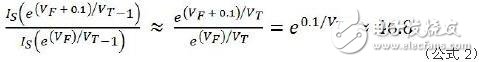
For example, a target LED current value of 20 mA will jump to 1A when its bias current exhibits a difference of only 0.1V. Even considering the actual RS value, a true LED device will have a 10 to 20-fold difference when it has a 0.1V offset difference.
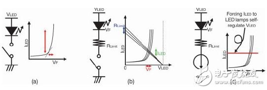
Figure 1. Comparing three LED driver circuits
Voltage source supporting current limit resistor
Now let's take a look at Figure 1b. Add a current limiting resistor RLIMIT to protect the LEDs. Due to the finite current resistor, the lamp will not be burned out. In the field of video display applications, this method is still not good enough to control the intensity of LED light. The LED curve and the load curve generated by RLIMIT determine its LED current value. As indicated by the red or blue mark, the LED and the resistor respectively have a forward voltage change and a resistance change due to manufacturing errors. These error factors can cause a non-negligible change in the LED current (green).
A constant current source
Figure 1c uses a constant current circuit instead of a resistor. The constant current driver circuit directly adjusts the LED current to a target value. Regardless of how many VF changes the LED lamp produces during the manufacturing process, the LED conducts a specific current value. The light intensity of the LED lamp is closely related to the charge passing through the PN junction, so the constant current driver is the ideal way to obtain a uniform light output from the LED lamp.
In addition, we all know that integrated circuits (ICs) can provide good matching circuit pairs. This is another advantage of choosing the constant current method. Figure 2 shows the basic output stage structure of an LED driver. Many LED driver ICs on the market have a reference current set terminal IREF, which is a constant current mirrored to its output.
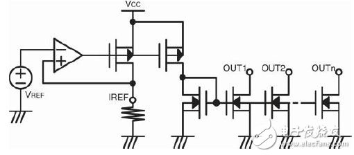
Figure 2. Basic Output Configuration of the LED Driver IC
Figure 2 is the result of this discussion, the basic output circuit configuration of the LED driver.
Color drive
So far, we have been able to determine how to drive a single LED light. The next step is to achieve full color light output for the video display system. Any color can be generated by combining different shades of light, red, green and blue (RGB). A more familiar example is the use of a color selection tool on a personal computer (PC).
Digital or analog grayscale control
The PC operating system mixes three colors into 256 levels (8 bits per order) or more to display full-color pixels. For LED display systems, the same concept of color-scale color intensity control is also required to achieve tone-level control or gray-scale control in the LED driver design.
First decide whether to use digital control or analog control. As mentioned earlier, the total number of charges passing through the PN junction determines the light intensity, so both digital and analog methods can control the light intensity. Figure 3 is a 50% gray scale control in digital and analog methods. In the overall 256 gradation example, the 50% indicates a target with 128 gray levels.
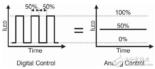
Figure 3. Digital and analog 50% intensity control
The PZDK series of smart chargers use high frequency switching rectification power modules. The charger is a smart charging device that was developed based on the technical requirements of the AGV (Automated Guided Vehicle) battery pack (group) charging. The working process of the charger is controlled by the microprocessor in real time, automatically turned on/off, and the operation is simple, safe and reliable. It uses a microprocessor as the main control unit and a color touch screen as a human-machine interface with flexible human-machine dialogue. The user can view the operating parameters and working status through the touch screen.


Lifepo4 Battery Charger,Scr Battery Charger,Lifepo4 Battery Packs Chargers,Thyristor Controlled Rectifier Charger
Xinxiang Taihang Jiaxin Electric Tech Co., Ltd , https://www.chargers.be