The op amp circuits we usually see are designed for conventional op amps around voltage input and voltage output. Another type of op amp is also commonly used in many audio processing applications. It operates with a voltage input, a current output (transconductance), and the gain is controlled by an external control. This device is called a transconductance operational amplifier (OTA). ), NE5517 is such an integrated circuit.
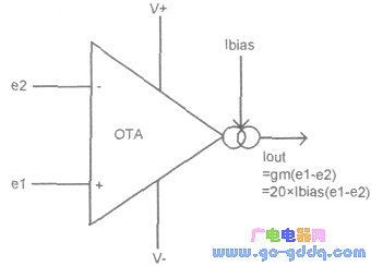
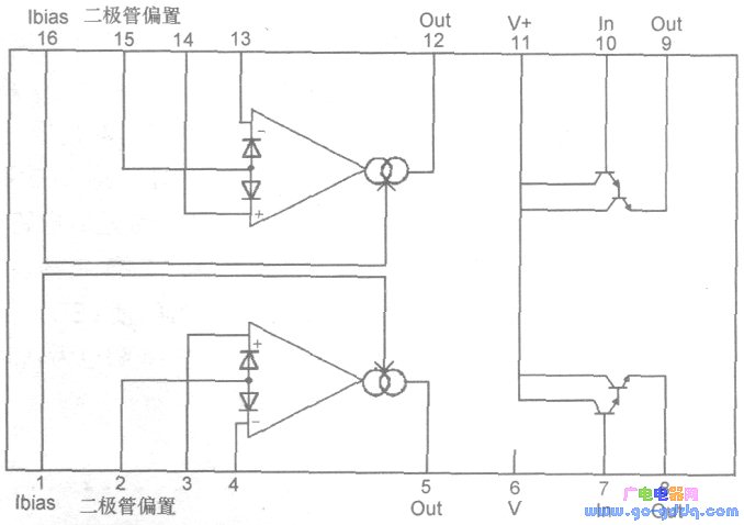
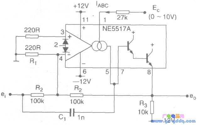
The figure above shows the circuit symbol of OTA and the basic calculation formula at work. The ordinary differential input receives two signals e1 and e2, and its output current is the difference between the two signals multiplied by the transconductance value of the OTA gm, the unit of gm It is Siemens (S), S = 1 / Ω. Gm is equal to 20 times the external bias current lbias. Therefore, the gain can be controlled by the bias current. In practical applications, the bias current can be arbitrarily changed in the range of 1000:1. The picture shows the pin and internal circuit diagram of the NE5517. Figure 3 shows a ring modulator circuit composed of an integrated NE5517 integrated circuit.
In the three channels below, the carrier signal is input by R2 and output by R3. The modulation voltage is input from pin 1 of the NE5517. When the modulation input is positive, the gain of the OTA rises, and the output current to R2 exceeds the direct input signal current of R2, and the carrier signal of the inverted output is obtained. Conversely, when the modulation voltage becomes negative, the OTA gain becomes smaller, and the direct signal current of R2 exceeds the current generated by the OTA output, and the in-phase carrier output signal is obtained.
Shenzhen Xcool Vapor Technology Co.,Ltd , https://www.szxcoolvape.com