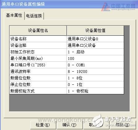
Siemens S7-300 communicates with Kunlun's on-state touch screen, requiring an RS232 or an RS485 time-matcher
The PROFIBUS-DP master can be a CPU with an integrated DP port (eg S7-300 315-2DP) or an S7-300 station with extended CP73-5, IM467, CP443-5Extend extended S7-400 station. The communication card CP5411, CP5511, CP5611, CP5611-A2, CP5412, CP5613 are inserted in the host computer, and also serve as the PROFIBUS-DP master station.
PROFIBUS-DP slaves include ET200 series, speed control devices, S7-200/300/400 stations and third-party equipment (eg S7200 PLC expansion EM277 communication module). A communication cable can also be made by yourself. If there are multiple PLCs, you can wire all 3 pairs of 3, 4 pairs 4, 5 pairs 5, 8 to 8.
Software condition(1) Operating system
The Windows 2000 Professional SP4 version or the Windows 98 SE operating system is recommended to use the Windows 2000 Professional SP4 operating system.
(2) Support software
Siemens SoftNet software must be installed and the SoftNet version is V5.3 Build 1381. The Siemens installation CD is: SIMATIC NET CD: 05/2000. What to install: In the CD directory: \sw \sn_pb_s7\ disk1\ Setup.exe CD directory: \sw \VBasic\ S7\disk1\ Setup.exe.
(3) PLC programming software
If the PROFIBUS-DP master uses an S7-300 PLC or an S7-400 PLC, you must have the programming software of Step7 5.0 or higher. Step7 V5.2 is recommended.
Note: The MCGS ProfibusDP driver calls SoftNet to implement communication. The version of SoftNet (V5.3 Build 1381) used has requirements for the operating system. It can only be used on Windows 2000 Pro or Windows 98 SE systems, but not for Windows 2000 Server. On Windows XP or newer operating systems.
The S7-300 PLC is the main station, the S7-200PLC expands the EM277 module as the slave station, and the host computer inserts the CP5611 communication card as an example to introduce the PROFIBUS-S7 communication steps in the MCGS.
Communication step1, S7-300 PROFIBUS parameter setting
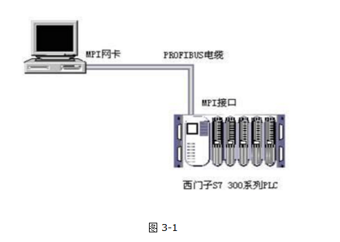
Step 1: Connect the hardware, including inserting the network card securely into the computer and connecting the PLC MPI port to the network card with a cable. The details are shown in Figure 3-1.
Step 2: Find “Set PG/PC interface†in the “Control Panel†of the computer, as shown in Figure 3-2, and open:
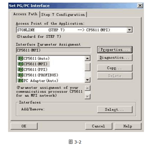
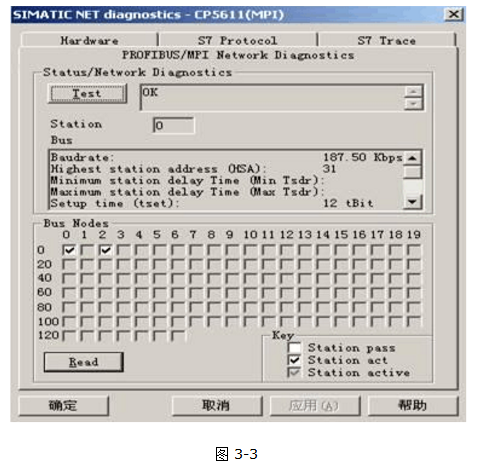
Select the "CP5611 (MPI)" mode. If the network card does not appear in the list, click on "Interfaces-Select" to install the network card. Then return, click "Diagnostics" and press "test". If you return "OK", press "Read" to detect the number of PLCs on the bus. The following shows that there is a PLC, the address of the network card is 0, S7-300 PLC The address of the MPI is 2. As shown in Figure 3-3:
Then exit and set the PROFIBUS parameters with the Step7 programming software.

Click Next: As shown in Figure 3-5:
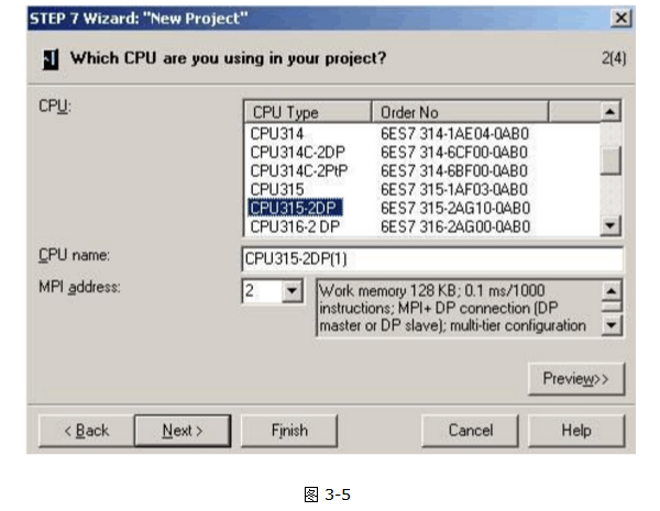
Select the currently connected PLC model and the MPI address of the tested PLC, and click “Nextâ€: as shown in Figure 3-6:
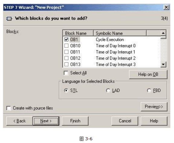
Click Next: as shown in Figure 3-7:
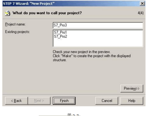
Fill in the name of the project and click "Finish". As shown in Figure 3-8:
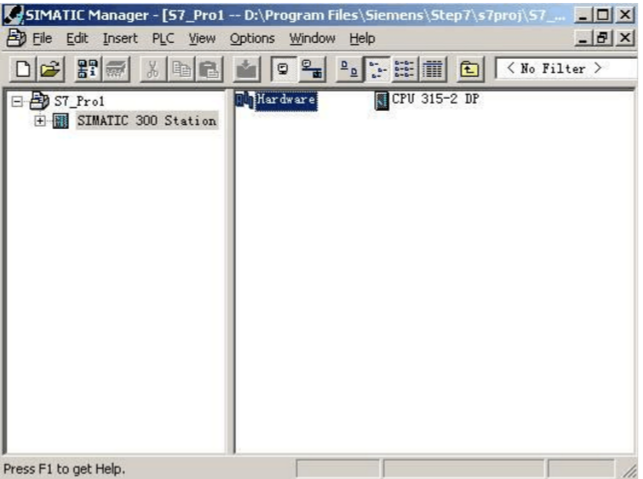
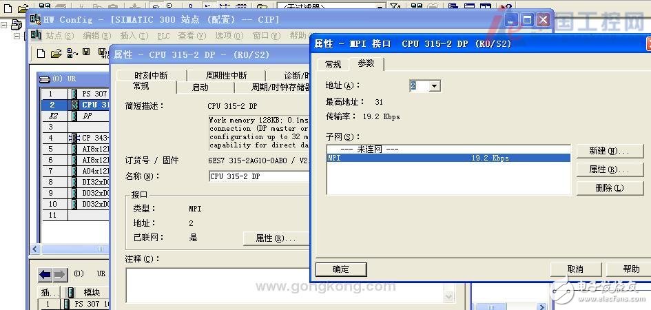
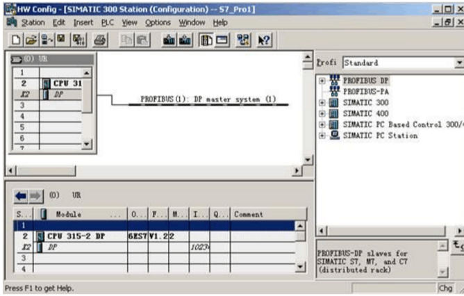
Double-click "Hardware" in 300 Station to configure the PLC hardware: as shown in Figure 3-9:
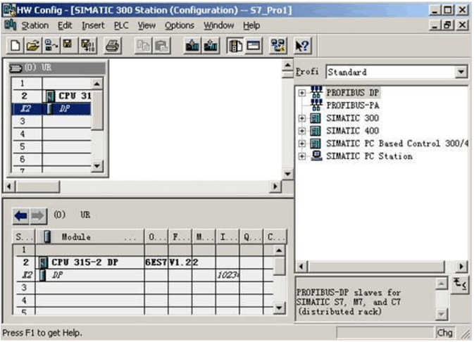
Since the S7315-2DP has one MPI port and one ProfiBus-DP port, the above figure lists two items. Double-click the DP item with the mouse: as shown in Figure 3-10:
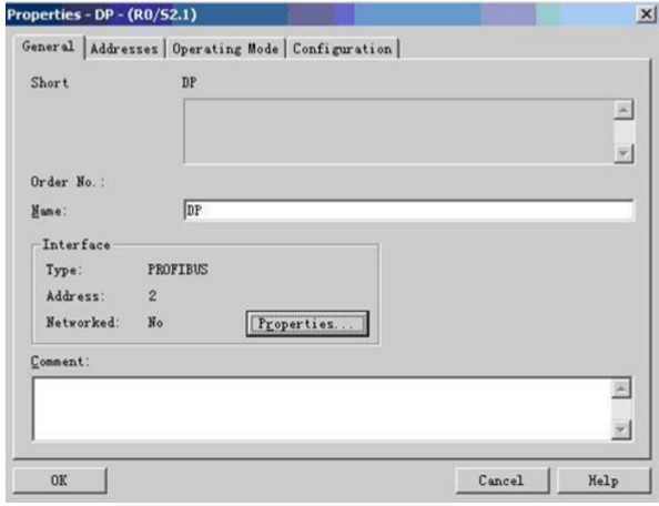
Click on the "Properties" option: as shown in Figure 3-11:
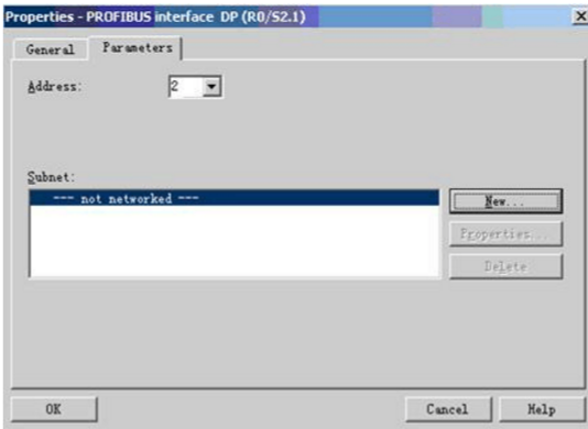
Click "New" to create a new Profibus network: as shown in Figure 3-12:
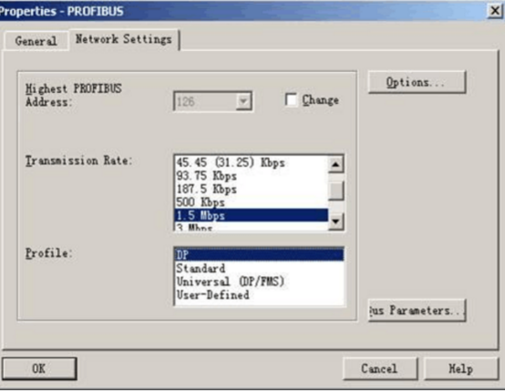
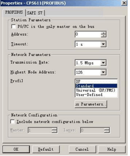
Select the transfer rate and profile of the Profibus network in the Network Settings project, then click ok to exit the Profibus network configuration. This is a DP-Master communication line in the hardware configuration window: as shown in Figure 3-13:
After the setup is complete, download the hardware configuration to the PLC and exit "SIMATIC Manage".
Note: If there is a battery in the PLC, these settings can be saved after power failure. If there is no battery in the PLC, the setting will be lost after power failure. It is recommended to install the battery to the PLC.
After the download is successful, connect the cable to the PLC DP communication port. If there is no battery, it can only be plugged in and out. It is easy to burn the DP port. Generally, do not do this.
2, S7-200 PROFIBUS parameter setting
Since the S7200PLC does not support the PROFIBUS communication method itself, it is necessary to extend a DP module EM277 without setting any special parameters.
3, COM S7 configuration
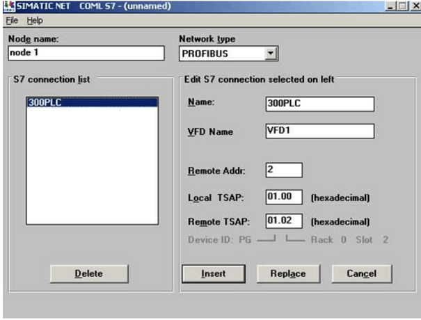
Step 1: Find SIMATIC NET in the Start menu to open the "COML S7" application:
Step 3: Open "SIMATIC Manage" in the start menu or on the desktop and the wizard dialog for creating a new project will pop up. As shown in Figure 3-4:
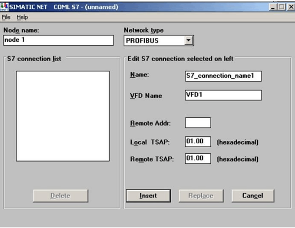
"Node Name": Any name can be used;
"Network type": Select PROFIBUS;
"Name": must be unique;
"VFD Name": Any name, multiple NAMEs can share a VFD Name, but no more than 8;
“Remote Addrâ€: The address name must be unique for the PLC (for the S7300, the Profibus address set in Hardware; for the S7200, the DM277 dialing address.);
"Local TSAP": no setting required;
“Remote TSAPâ€: Four hexadecimal numbers separated by “.â€.
The second digit indicates the type of remote site: 0-PS, 1-PG, 2-OS; the third digit indicates the RACK number of the CPU of the PLC, and the fourth digit indicates the SLOT number of the CPU. If it is the S7200, it does not need to be changed. If the S7300 is normally set to 01.02 or 02.02;
Step 2: Click “Insert†to insert after the setting is completed.
If there are multiple PLCs, continue to set, click "Insert" once for each setting.
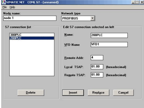
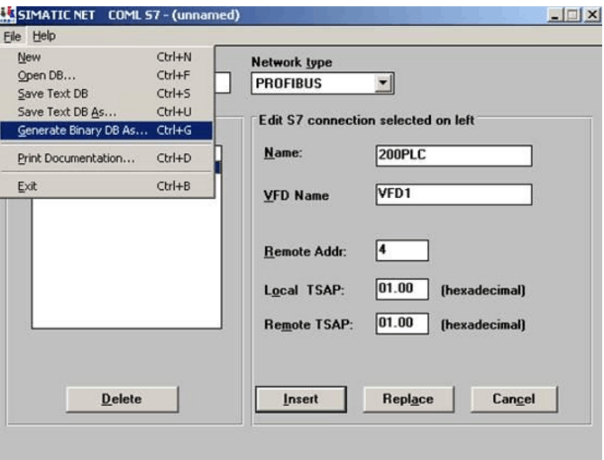
Step 3: After all the PLCs are added, in the File menu, select Generate Binary DB As to generate the binary database *.ldb file.
4, Set PG / PC Iterface configuration
Go to the Control Panel, select and open Set PG/PC Iterface, configure the communication card PROFIBUS, and select "CP_L2_1-"CP5611 (PROFIBUS)" for the access point:
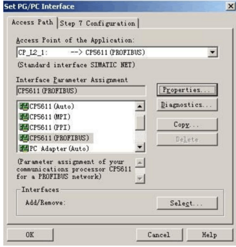
Click Properties to set the Properties property:
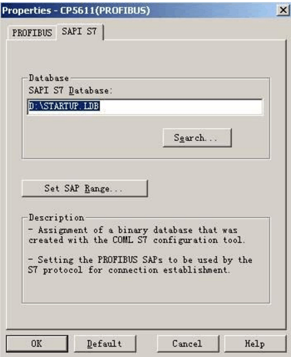
Search for and select the *.ldb file generated in the COM S7 configuration in the SAPI S7 item:
Click the "diagnostics" button to diagnose:
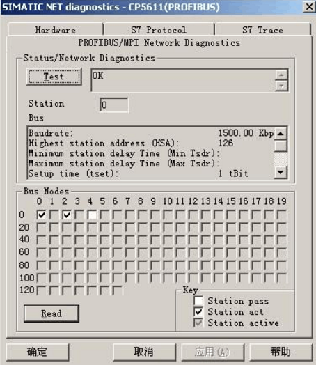
Press "test", if you return "OK", click "Read" to detect the number of PLCs hanging on the bus. The following shows that there are 2 PLCs, one is S7300, the ProfiBus address is 2, and one is S7200, ProfiBus address 4,0 is the address of the CP5611 network card.
5, MCGS equipment component setting steps
5.1 Selecting Communication Device Components
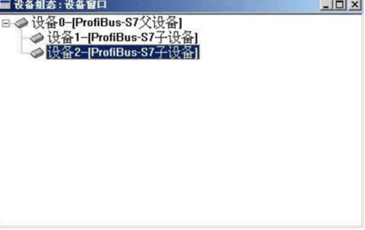
In the device toolbox, "ProfiBus-S7 parent device", "ProfiBus-S7 child device" is loaded from the device toolbox "PLC device\Siemens\ProfiBusNT device\Profibus-S7 parent device and \Profibus-S7 child device directory" In the Selected Devices window, press OK and add the parent and child devices to the device window, and if multiple PLCs, add multiple child devices.
Note: The driver in the driver list "ProfiBusNT Device" directory is used on the operating system Windows 2000. The driver in the "ProfiBus98 Device" directory is used on the operating system 98. Please make the correct choice according to the situation.
5.2 Profibus-S7 sub-device property settings:
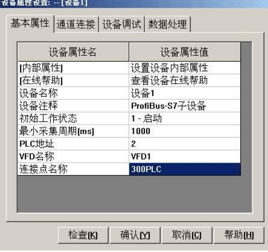
(1) Device Name: The device can be renamed as needed, but it cannot be the same name as other device components already in the device window.
(2) Initial working state: It is used to set the initial working state of the device. When it is set to start, when entering the MCGS operating environment, MCGS will automatically start to operate the device. When set to stop, MCGS does not operate the device, but The MCGS device operation functions and policies can be used to start or stop the device in the MCGS runtime environment.
(3) Minimum acquisition period: The time period in which MCGS operates the device during operation, in milliseconds. Since communication is generally set to 1000ms during static measurement and 10ms for fast measurement.
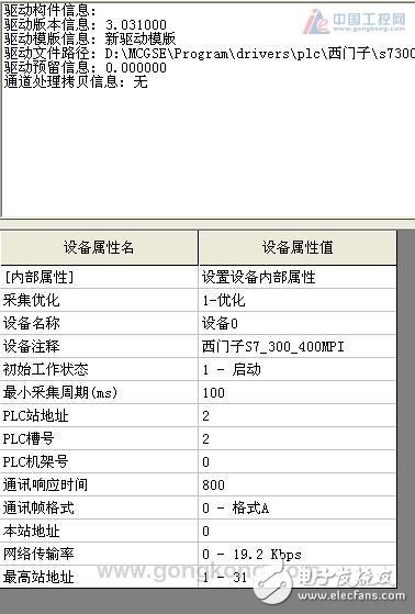
(4) PLC address: The address of PLC in S7200 is the address of EM277. In S7300, the address is the ProfiBus address of PLC.
(5) VFD name: It must correspond to the COM S7 configuration. If the error is written or not, the communication will fail.
(6) Connection point name: It must correspond to your configuration in COM S7. If the error is written or not, the communication will fail.
5.3 Internal properties
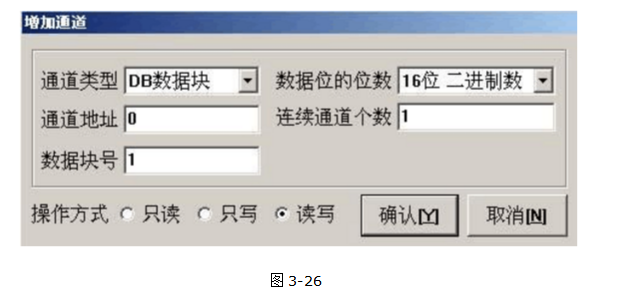
Click “Set Internal Attribute of Device†in the basic property page of the device to set the read/write channel of the PLC, so that the device channel connection can be made later, so that the data in the device can be sent to the specified data object in the real-time database or the data object. The value is fed into the channel output specified by the device.
Siemens PROFIBUS-S7 protocol PLC device components divide the PLC channel into read-only, write-only and read-write three. The read channel is used to read the data in the PLC into the real-time database of MCGS, and the write channel is used to store MCGS in real time. The data in the database is written into the PLC. The read and write functions are both read and write. Generally, the first read first. After that, if the MCGS variable needs to be changed, it is written. If the MCGS variable has not changed, read from the PLC. Come back, and update the current MCGS variable value, the device component can operate the PLC's registers are:
(1) Input, output, and intermediate registers.
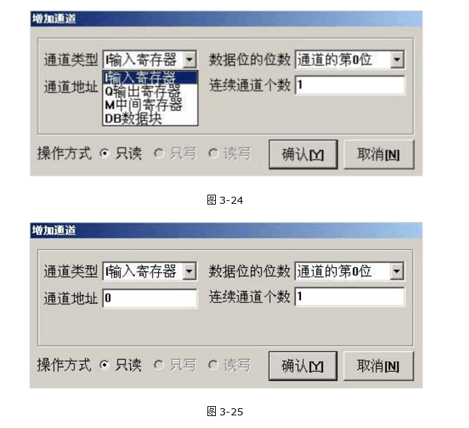
(2) Any data block defined in the PLC: such as DB1, DB2, DB3 but the maximum data block number cannot exceed 512, that is, DB512. In the S7200, there is only DB1, and DB1 corresponds to the V data area.
General Purpose Frequency Inverter
General Purpose Frequency Inverter,Three Phase Variable Frequency Converter,Triple Phase Frequency Converter,Single Phase Frequency Inverter
Zhejiang Kaimin Electric Co., Ltd. , https://www.ckmineinverter.com