The load is required to measure the output energy or energy consumption of AC-DC and DC-DC power supplies, power devices, batteries, battery chargers, etc. The conventional method is to use fixed resistors and variable resistors to act as the load under test. An emerging electronic instrument and test equipment, the electronic load came into being, he used the power device analog resistor, which has strong operational flexibility. At present, the development of electronic load technology is relatively mature. Generally, there are working modes such as constant current (CC), constant resistance (CR), constant voltage (CV), and constant power (CP). Researching and developing new low-cost electronic loads has also become a meaningful undertaking.
1 Constant current type (CC) electronic load structure block diagram introduction
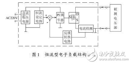
The constant current (CC) electronic load is a specialized device used to test various properties of a voltage source. This paper introduces a new scheme of constant current electronic load. Based on the feedback control theory, it uses the analog PI regulator to control the conduction strength of the N-channel high-power MOSFET DE to achieve the static-free control of the measured current. The control precision is high, the circuit is simple, and the cost is low. Figure 1 is a block diagram of the structure of a constant current type electronic load. The DC stabilized power supply box is a DC stabilized power supply circuit. It provides a constant current setting voltage, a working voltage of the PI regulator, a current detection and conversion circuit, and requires a power output and a high voltage stability indicator. . The constant current setting circuit provides a linear adjustable negative voltage output. The PI regulator consists of a common operational amplifier, and the PI parameters are optimally tuned experimentally. The actuator is an N-channel MOS transistor or a MOS transistor group.
2 Control circuit design and experimental research
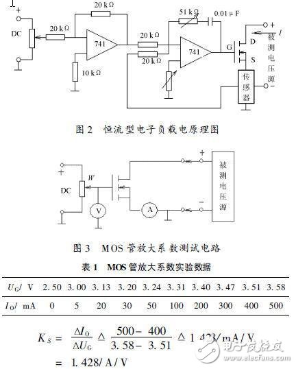
In order to achieve a control without static adjustment, it is necessary to use proportional integral) differential control law. For this control object, proportional (integral) (PI) control can meet the requirements. The hardware circuit is shown in Figure 2. The circuit is mainly composed of an inverter, a PI regulator, a MOS transistor and a Hall current sensor. The design time is generally performed from a control object or an execution unit. The first thing that needs to be determined is the transfer function of the execution unit, ie the determination of the amplification factor Ks of the MOS tube.
2.1 Determination of the amplification factor KS of the MOS tube
The test circuit is shown in Figure 3. The measured voltage source power is large enough and the output current meets the test requirements. Adjusting the given potentiometer W, measuring the MOS tube G pole voltage UG and the current IO flowing through the MOS tube DS pole to obtain a set of experimental data recorded in Table 1, as can be seen from the table, when UG ≤ 2. 5 V When the MOS transistor is not turned on, IO = 0 is called dead zone. After UG "2.5 V, the MOS tube starts to conduct. When UG" 3. 3 V, the relationship changes linearly. Find KS in the linear segment.
2.2 Determination of current feedback coefficient β
That is, the determination of the conversion coefficient of the Hall current sensor. The current sensor used in the design is a Hall sensor. The input is current and the output is voltage. The Hall coefficient K = 0. 8 V/A is determined by the test, that is, when the input current of the sensor is 1 A, the voltage at the output terminal. 0.8V.β= K = 0. 8 V/A
2.3 Determination of static amplification factor KP of PI regulator
According to the negative feedback closed-loop control principle: K = βKP KS = 1 Get: KP = 1 / βKS△0. 875V / A. According to this value, select the regulator input and output resistance values ​​to meet RF / RI = KP.
2.4 Brief description of the determination and control principle of each voltage polarity
The polarity of each voltage is generally pushed back and forward. The control voltage UG of the MOS transistor is positive (+), which requires the output of the PI regulator to be positive (+). Considering that the output of the Hall current sensor is always Positive ( + ), in order to constitute a negative feedback control, the given voltage of the PI regulator should be negative ( - ). Therefore, the PI regulator adopts a negative phase input, and the adjustable positive voltage generated by the potentiometer W is changed to an adjustable negative voltage by the inverter of the previous stage, and is added as a constant current setting value to the input pole of the regulator, and The current feedback voltage provided by the Hall current sensor is compared, and the proportional integral adjustment is implemented by the PI regulator according to the deviation amount and the positive and negative polarity to achieve constant current (IO). Change the size of the integral capacitor to meet the response speed and stability requirements.
3 Experimental research results
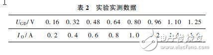
Table 2 is the experimental measured data. From the data law, UGD (potentiometer W) and MOS tube leakage and source current IO have a good linear relationship. And IO / UGD = 1 / β = 1 / 0. 8 = 1. 25. The rapid response and anti-interference performance of the adjustment response in the experiment can be adjusted to the best.
4 Notes and improvements
(1) Due to the use of the PI regulator, the dead zone of the MOS transistor does not have to be specially designed to eliminate, and the nonlinearity of the MOS transistor is eliminated by itself in the closed loop.
(2) According to the nature of the device under test (resistance, inductive, capacitive), the PI parameters can always be adjusted to ensure its rapidity, stability and immunity requirements.
(3) The system has strong scalability. Digital reference and adjustment control can be realized.
Nowadays, users buying a new type of Bluetooth Speaker are not only based on functional considerations to meet product requirements, but their biggest purchase motivation, their inner psychological appeal and emotional resonance are one of the motives.
What are the characteristics/attributes of Bluetooth speakers?
1. Mini appearance, light and portable;
2. Bluetooth pairing makes listening to music more convenient;
3. Freely switch to answer mobile phone calls;
4. Long press the volume key to adjust the size;
5. Stereo sound, sensory experience;
6. Support TF card, and insert AUX audio music insert function, compatible with a variety of music formats, listen to the music you want at any time.
7.We also use waterproof material to make it, and the waterproof grade reaches IPX4, which can prevent rain or domestic water from splashing on the speaker. When using it, remember to close the charging rubber plug.
No matter how you listen to the music in your mobile phone, it seems like you are rewinding. The Bluetooth speaker restores the concert scene for you. If you are tired of listening to the same old tune of the music APP, it is better to feel the scene of the Vienna Concert Hall at home.
Portable Wireless Bluetooth Speaker,Bluetooth Speaker With LED Light,Bluetooth Speaker With LED Light
Shenzhen Focras Technology Co.,Ltd , https://www.focras.com