Introduction to the principle of codec chip PT2262/PT2272 chip
This article refers to the address: http://
PT2262/2272 is a low-power low-cost general-purpose codec circuit manufactured by Pucheng Company of Taiwan. The PT2262/2272 can have up to 12-bit (A0-A11) tri-state address pin (suspended, connected). High level, connected to low level), any combination can provide 531441 address code, PT2262 can have up to 6 bits (D0-D5) data terminal pin, set address code and data code serial output from 17 feet, available For wireless remote control transmitter circuits. The encoded signal sent by the encoding chip PT2262 consists of: address code, data code, and synchronization code to form a complete codeword. After the decoder chip PT2272 receives the signal, the address code is compared and verified by the two times, and the VT pin outputs a high level. At the same time, the corresponding data pin also outputs a high level. If the transmitting end keeps pressing the button, the encoding chip will also continuously emit. When the transmitter does not press the button, the PT2262 is not connected to the power supply, and its 17 pin is low level, so the 315MHz high frequency transmitting circuit does not work. When there is a button press, the PT2262 is powered, and the 17th pin outputs The modulated serial data signal, when the 17-pin is high level, the 315MHz high-frequency transmitting circuit starts to oscillate and emits a constant-amplitude high-frequency signal. When the 17-pin is low-level, the 315MHz high-frequency transmitting circuit stops oscillating, so it is high. The frequency transmitting circuit is completely controlled by the digital signal outputted by the 17-pin of the PT2262, so that the amplitude keying (ASK modulation) of the high-frequency circuit is equivalent to the amplitude modulation of 100% modulation.
PT2262 features
1, CMOS process manufacturing, low power consumption
2, less external components
3, RC oscillator resistance
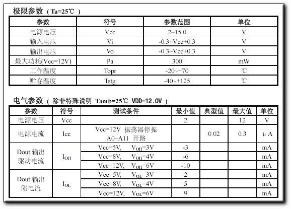
4, the working voltage range is wide: 2.6-15v
5, the data can be up to 6
6, the address code can be up to 531,441
Application range
1. Vehicle anti-theft system
2, home security system
3, remote control toys
4, other electrical remote control
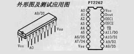
A0-A111-8, 10-13 address pins, used for address coding, can be set to "0", "1", "f" (floating),
D0-D57-8, 10-13 data input, there is a "1" that has coded output, internal pulldown
Vcc18 power positive terminal (+)
Vss9 power supply negative (-)
TE14 coding start end, used for multi-data coded transmission, active low;
OSC116 oscillating resistor input terminal, and the resistance connected to OSC2 determines the oscillation frequency;
OSC215 oscillatory resistor oscillator output;
Dout17 coded output (low level when normal)
In specific applications, the external oscillating resistor can be adjusted as needed.
The larger the resistance, the slower the oscillation frequency, the larger the width of the code, and the longer the time to send a frame.
Most of the products on the website are combined with 2262/1.2M=2272/200K.
A small amount of products use 2262/4.7M=2272/820K.

Name pin description
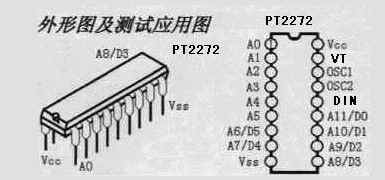
A0-A111-8, 10-13 address pins, used for address coding, can be set to "0", "1", "f" (floating), must be consistent with 2262, otherwise not decoded
D0-D57-8, 10-13 address or data pin, when used as data pin, only when the address code is consistent with 2262, the data pin can output the high level corresponding to the data end of 2262, otherwise the output is low. Flat, the latch type can only be converted after receiving the next data.
Vcc18 power positive terminal (+)
Vss9 power supply negative (-)
DIN14 data signal input from the output of the receiver module
OSC116 oscillating resistor input terminal, and the resistance connected to OSC2 determines the oscillation frequency;
OSC215 oscillatory resistor oscillator output;
VT17 decoding valid confirms the output (normally low) decoding effectively becomes high (transient)

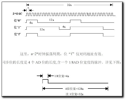
Both the address code and the data code are represented by pulses of different widths, and two narrow pulses represent "0";
Two wide pulses indicate "1"; a narrow pulse and a wide pulse indicate "F", which is the "floating" of the address code.
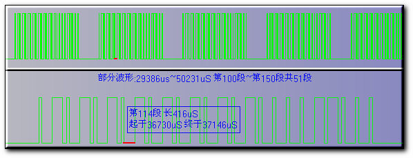
The above is a segment of the waveform that we intercepted from the signal output pin of the super regenerative receiver module. It can be clearly seen.
The upper part of the figure is a group of words, each group of codes is separated by a synchronization code, so if we use the single-chip software to decode, the program only needs to judge the synchronization code, and then pulse width of the following words. Just recognize it.
The lower part of the figure is an enlarged set of words: one word is encoded by a 12-bit AD code (address code plus data code,
For example, an 8-bit address code plus a 4-bit data code, each AD bit is represented by two pulses:
Two narrow pulses indicate "0"; two wide pulses indicate "1";
A narrow pulse and a wide pulse indicate "F", which is the "dangling" of the address code.
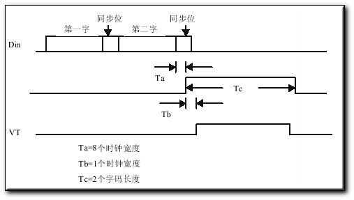
2262 emits at least 4 groups of codes each time it is transmitted. 2272 only detects the same address code plus data code twice in succession to drive the "1" in the data code to the corresponding data output terminal and drive the VT terminal. Sync is high.
Because of the characteristics of wireless transmission, the first set of words is very susceptible to zero-level interference, which often produces errors.
So the program can discard the processing.

The PT2272 decoder chip has different suffixes, indicating different functions, with L4/M4/L6/M6 points.
Where L represents the latched output, and the data can maintain the corresponding level state as long as it is successfully received.
It changes until the next time the remote control data changes. M represents a non-latched output,
The level of the data pin output is instantaneous and corresponds to whether the transmitter is transmitting, and can be used for jog-like control. The suffixes 6 and 4 indicate that there are several parallel control channels.
When using 4 channels of parallel data (PT2272-M4), the corresponding address code should be 8 bits.
If 6 channels of parallel data are used (PT2272-M6), the corresponding address code should be 6 bits.
Address code setting and modification of PT2262/2272 chip:
In normal use, we generally use 8-bit address code and 4-bit data code. At this time, the first to eighth pins of the encoding circuit PT2262 and the decoding PT2272 are address setting pins. There are three states to choose from: floating, positive power supply Three states are grounded, and the 8th power of 3 is 6561. Therefore, the address coding non-repetition is 6561. Only the address codes of the transmitting end PT2262 and the receiving end PT2272 are identical, and can be paired. The manufacturer of the remote control module is convenient for production. management,
The eight-digit address encoding ends of the PT2262 and PT2272 of the remote control module are all suspended at the factory.
In this way, the user can conveniently select various encoding states, and if the user wants to change the address encoding,
Just set the 1st to 8th pins of PT2262 and PT2272 to be the same.
For example, connect the pin 1 of the PT2262 of the transmitter to the positive power supply, and the other pins are suspended.
Then the PT2272 of the receiver is connected to the positive power supply as well as the fifth pin of the first leg.
Pairing reception is achieved when other pins are left floating. When the address codes of the two are completely identical, the corresponding D1 to D4 terminals of the receiver output an about 4V interlock high level control signal, and the VT terminal also outputs a decoded effective high level signal.
The user can add these signals to the first level to drive the relay, power triode, etc. for load remote control switch operation.
The remote control products provided on our website generally reserve the address coding area and use solder lap welding to select:
Suspended, connected to the power supply, grounding three states, the factory is generally suspended,
It is convenient for customers to modify the address code themselves. Here we take the jumper area of ​​the commonly used super regenerative pin receiving board A-L4 as an example:
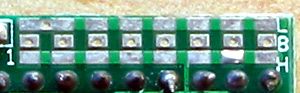
Users can see that the jumper area is composed of three rows of pads, the middle of the eight pads is the first to eighth feet of the PT2272 decoder chip, the first one on the left is the first foot of the chip, the top one The row of pads is marked with the letter L, indicating that it is connected with the power ground. If it is measured with a multimeter, it will be found together with the 9th pin of the PT2272; the bottom row of pads is marked with the H mark, indicating that it is connected with the positive power supply.
If you use a multimeter to measure it, it will be found together with the 18th pin of PT2272. The so-called address code is to short the upper and lower pads with solder by solder, for example, short the first leg and the upper pad L with solder. After that, it is equivalent to setting the first leg of the PT2272 chip to ground. Similarly, short-circuiting the first pin and the lower pad H with solder is equivalent to setting the first leg of the PT2272 chip to be connected to the positive power supply. If it is not connected, it means that it is floating.
The principle of setting the address code is: the same system address code must be consistent;
Different systems can be distinguished by different address codes. As for what kind of address code is set, it is completely like the customer.
The PT2262 and PT2272 must be identical in their address codes. The oscillating resistors must also match.
Otherwise, the receiving distance will become close or even unacceptable. With the development of technology, a number of compatible chips appear on the market.
In actual use, as long as the oscillating resistor is slightly modified, it can be used together. According to the actual experience of our website,
The following parameters match better:
Coded transmitter chip
Coded receiver chip
PT2262PT2260SC2260SC2262CS5211PT2272/SC2272/CS5212
1.2M without 3.3M1.1M1.3M200K
1.5M without 4.3M1.4M1.6M270K
2.2M without 6.2M2M2.4M390K
3.3M without 9.1M3M3.6M680K
4.7M1.2M12M4.3M5.1M820K
2262 IR is a dedicated chip for the 2262 series for infrared remote control. It can be wired according to the following drawings.
The receiving distance can be farthest by adjusting the size of the Rosc resistor at the transmitting end, and the adjustment range of the transmitting end resistance is 390 to 420K.


The SC series chip, which is fully compatible with the PT2262/2272 chip, can directly replace the PT series chip.
No changes are needed on the periphery, but the price is much cheaper than the PT series.

Hd Led Display has advantages such as high refresh rate, high gray level, utilization of high brightness, trace free, lower consumption and EMI, HD Led Display is used in indoor without glare. HD Led Display is popular as light weight, thickness, high precision and less space usage at shipping. The natural color rendition and real seamless splicing can make HD led display use for TV station show that with the noiseless design and high-efficiency cooling performance. Besides offering complete and best solutions,Shenzhen Cxcolor Optoelectronic Company limited is a professional manufacturer specialized in Led Display Screen,LED stage rental display screen,Led Advertising Display screen,small pitch LED display screen,LED transparent display screen,HD Led Display,vehicle LED display screen,LED spherical display screen,LED energy-saving display screen.

HD Led Display
Hd Led Display,Hd Small Pitch Led Display,Flexible Led Video Display,Hd Led Screen Display
Shenzhen Cxcolor Optoelectronics Co., LTD. , http://www.largeledscreen.com