The inductance of ultra-low power or ultra-high power switching power supplies is not as easy to select as a typical switching power supply. At present, conventional inductors are manufactured for some mainstream designs and are not well suited for some special designs. This paper focuses on the inductor selection problem of ultra-low power, ultra-high efficiency Buck circuits. A typical application example is a small-volume battery that is powered for a long time. In this kind of circuit, the problem that makes engineers feel difficult is mainly the contradiction between battery capacity (cost and volume) and Buck circuit volume and efficiency. In order to reduce the size of the switching power supply, it is best to choose the highest possible switching frequency. However, the switching loss and the loss of the output inductor increase with the increase of the switching frequency, and it is likely to become the main factor affecting the efficiency. It is these contradictions that greatly increase the difficulty of circuit design.
Inductor Requirements for Buck Circuits For engineers, ferromagnetic components (inductors) may be the earliest contact nonlinear devices. However, according to the data provided by the manufacturer, it is difficult to predict the loss of the inductor at high frequencies. Because manufacturers usually only provide parameters such as open circuit inductance, operating current, saturation current, DC resistance, and self-excited frequency. For most switching power supply designs, these parameters are sufficient, and choosing the right inductor based on these parameters is also very easy. However, for ultra-low current, ultra-high frequency switching power supplies, the nonlinear parameters of the inductor core are very sensitive to frequency, and secondly, the frequency also determines the coil loss.
For ordinary switching power supplies, core losses are almost negligible relative to DC I2R losses. Therefore, in general, in addition to the frequency-dependent parameters of "self-excited frequency", the inductance has almost no other frequency-related parameters. However, for ultra-low power, ultra-high frequency systems (battery-powered devices), these high frequency losses (core loss and coil losses) are typically much greater than DC losses.
Coil losses include DC I2R losses and AC losses. Among them, AC loss is mainly caused by skin effect and proximity effect. The skin effect means that the electric charge moving with the increase of the frequency tends to flow toward the surface of the conductor, which is equivalent to reducing the cross-sectional area of ​​the conductor conduction and improving the AC impedance. For example, at 2MHz, the conductive depth of the conductor (vertically downward from the conductor surface) is only about 0.00464 cm. This causes the current density to drop to 1/e (about 0.37). Proximity effect means that the magnetic field generated by the current in the adjacent wires of the inductor will affect each other, resulting in a so-called "crowded current", which also increases the AC impedance. For the skin effect, moderate relief can be achieved by multi-core wires (multiple thin wires in the same wire). For circuits where the AC current ripple is much smaller than the DC current, multi-core wires can effectively reduce the total loss of the inductor.
Core loss is mainly due to hysteresis and mutual inductance of the core's internal conductivity or other nonlinear parameters. In the Buck topology, the BH hysteresis loop of the first quadrant has the greatest influence on the core loss. In the partial view of the first quadrant, the hysteresis loop shows the process of the inductor transitioning from the initial inductance to the peak inductance and back to the initial inductance. If the switching power supply is stable in a discontinuous state, the hysteresis loop will transition from the residual inductance (Br) to the peak inductance (refer to Figure 1). If the switching power supply is operating in a continuous state, the hysteresis loop will rise from the DC bias point to the peak of the curve and back to the DC bias point. The exact curve shape of the hysteresis loop (essentially an elliptical curve) can be determined experimentally.
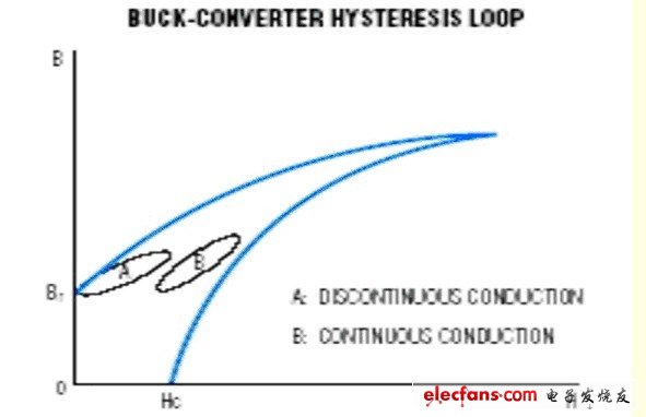
Figure 1 A Buck circuit inductance BP hysteresis loop Most of the core is composed of a powdery magnetic material and a bonding material such as ceramic. An unused magnetic core can be simply imagined as a large number of magnetic needles wrapped by a thin layer of adhesive material, independent of each other, and having random orientation. Since there is no unified model that can explain the core loss well, the above empirical model is used to explain the core loss. In the last reference of this paper, there is a deeper core model for the reader's reference.
Adjacent magnetic needles with similar magnetic directions interact with each other to form an "alliance". Although these magnetic needles are wrapped by an adhesive material and are physically independent of each other, the magnetic fields between them are interrelated. We call these "alliance" "units." The boundary of the unit is the split surface of the internal "alliance" and the external magnetic needle. Magnetic needles outside the boundaries of the unit are more difficult to unite with the "alliance" within the boundary. We call these boundaries "cell walls", which are often used to explain many of the basic parameters of a magnetic core.
When a magnetic field is applied to the magnetic core (current is applied to the coil), cells having different directions are associated with each other. When a sufficiently strong current forms an applied magnetic field, the cells that are close to the coil are at a stronger magnetic field and will first form a joint (a larger unit). At this time, the unit on the deeper level has not been affected by the magnetic field. The cell walls between the unit and the unaffected unit continue to move toward the center of the core under the action of a magnetic field. If the current in the coil is not undone or flipped, the entire core will be united. The magnetic needles of the entire core are joined together and we call them "saturation." The BH hysteresis loop given by the inductor manufacturer represents the process of the core from the initial stage of magnetization to the saturation stage. If the current is weakened, the unit will transition to a free initial state, but some units will continue to remain in a combined state. This incomplete conversion is remanence (can be seen in the hysteresis loop). This remanence phenomenon is manifested as stress at the next unit bonding, resulting in core loss.
The hysteresis loss in each cycle is:
WH=mH&TImes;dI
The integral in the equation is the enclosed area in the hysteresis loop, the core from the initial inductance to the peak inductance, and then back to the initial inductance. The energy loss at the switching frequency of F is:
PH = F&TImes;mH&TImes;dI
Calculating these AC losses seems easy. However, under high frequency and medium current density, the situation will be extremely complicated. Each circuit has some parameters that affect the core loss, and these parameters are generally difficult to quantify. For example: discrete capacitors, PCB layout, drive voltage, pulse width, load status, input and output voltage, etc. Unfortunately, core losses are severely affected by these parameters.
Each core material has a non-linear conductivity that can cause losses. It is this conductivity that induces a loss of "eddy current" inside the core due to the applied magnetic field. At a constant magnetic flux, the core loss is roughly proportional to the frequency nth power. The index n will vary with the core material and the manufacturing process. The usual inductor manufacturer fits the empirical approximation formula through the core loss curve.
The inductance parameter magnetic induction B can be expressed by the following equation in the forward switching circuit:
Bpk = Eavg/(4&TImes;A×N×f)
Where Bpk is the peak AC flux density (Teslas); Eavg is the average AC voltage per half cycle; A is the core cross-sectional area (m2); N is the number of turns of the coil; f is the frequency (Hz).
In general, magnetic material manufacturers evaluate the core's rated inductance - AL. The inductance can be easily calculated by AL.
L = N2AL
Among them, AL is proportional to the doping degree of the magnetic material, and is also proportional to the cross-sectional area of ​​the magnetic core divided by the length of the magnetic circuit. The total loss of the core is equal to the volume of the core multiplied by Bpk times the frequency in watts/m3. It is closely related to manufacturing materials and manufacturing processes.
Inductor Requirements for Buck Circuits For engineers, ferromagnetic components (inductors) may be the earliest contact nonlinear devices. However, according to the data provided by the manufacturer, it is difficult to predict the loss of the inductor at high frequencies. Because manufacturers usually only provide parameters such as open circuit inductance, operating current, saturation current, DC resistance, and self-excited frequency. For most switching power supply designs, these parameters are sufficient, and choosing the right inductor based on these parameters is also very easy. However, for ultra-low current, ultra-high frequency switching power supplies, the nonlinear parameters of the inductor core are very sensitive to frequency, and secondly, the frequency also determines the coil loss.
For ordinary switching power supplies, core losses are almost negligible relative to DC I2R losses. Therefore, in general, in addition to the frequency-dependent parameters of "self-excited frequency", the inductance has almost no other frequency-related parameters. However, for ultra-low power, ultra-high frequency systems (battery-powered devices), these high frequency losses (core loss and coil losses) are typically much greater than DC losses.
Coil losses include DC I2R losses and AC losses. Among them, AC loss is mainly caused by skin effect and proximity effect. The skin effect means that the electric charge moving with the increase of the frequency tends to flow toward the surface of the conductor, which is equivalent to reducing the cross-sectional area of ​​the conductor conduction and improving the AC impedance. For example, at 2MHz, the conductive depth of the conductor (vertically downward from the conductor surface) is only about 0.00464 cm. This causes the current density to drop to 1/e (about 0.37). Proximity effect means that the magnetic field generated by the current in the adjacent wires of the inductor will affect each other, resulting in a so-called "crowded current", which also increases the AC impedance. For the skin effect, moderate relief can be achieved by multi-core wires (multiple thin wires in the same wire). For circuits where the AC current ripple is much smaller than the DC current, multi-core wires can effectively reduce the total loss of the inductor.
Core loss is mainly due to hysteresis and mutual inductance of the core's internal conductivity or other nonlinear parameters. In the Buck topology, the BH hysteresis loop of the first quadrant has the greatest influence on the core loss. In the partial view of the first quadrant, the hysteresis loop shows the process of the inductor transitioning from the initial inductance to the peak inductance and back to the initial inductance. If the switching power supply is stable in a discontinuous state, the hysteresis loop will transition from the residual inductance (Br) to the peak inductance (refer to Figure 1). If the switching power supply is operating in a continuous state, the hysteresis loop will rise from the DC bias point to the peak of the curve and back to the DC bias point. The exact curve shape of the hysteresis loop (essentially an elliptical curve) can be determined experimentally.
Figure 1 A Buck circuit inductance BP hysteresis loop Most of the core is composed of a powdery magnetic material and a bonding material such as ceramic. An unused magnetic core can be simply imagined as a large number of magnetic needles wrapped by a thin layer of adhesive material, independent of each other, and having random orientation. Since there is no unified model that can explain the core loss well, the above empirical model is used to explain the core loss. In the last reference of this paper, there is a deeper core model for the reader's reference.
Adjacent magnetic needles with similar magnetic directions interact with each other to form an "alliance". Although these magnetic needles are wrapped by an adhesive material and are physically independent of each other, the magnetic fields between them are interrelated. We call these "alliance" "units." The boundary of the unit is the split surface of the internal "alliance" and the external magnetic needle. Magnetic needles outside the boundaries of the unit are more difficult to unite with the "alliance" within the boundary. We call these boundaries "cell walls", which are often used to explain many of the basic parameters of a magnetic core.
When a magnetic field is applied to the magnetic core (current is applied to the coil), cells having different directions are associated with each other. When a sufficiently strong current forms an applied magnetic field, the cells that are close to the coil are at a stronger magnetic field and will first form a joint (a larger unit). At this time, the unit on the deeper level has not been affected by the magnetic field. The cell walls between the unit and the unaffected unit continue to move toward the center of the core under the action of a magnetic field. If the current in the coil is not undone or flipped, the entire core will be united. The magnetic needles of the entire core are joined together and we call them "saturation." The BH hysteresis loop given by the inductor manufacturer represents the process of the core from the initial stage of magnetization to the saturation stage. If the current is weakened, the unit will transition to a free initial state, but some units will continue to remain in a combined state. This incomplete conversion is remanence (can be seen in the hysteresis loop). This remanence phenomenon is manifested as stress at the next unit bonding, resulting in core loss.
The hysteresis loss in each cycle is:
WH=mH&TImes;dI
The integral in the equation is the enclosed area in the hysteresis loop, the core from the initial inductance to the peak inductance, and then back to the initial inductance. The energy loss at the switching frequency of F is:
PH = F&TImes;mH&TImes;dI
Calculating these AC losses seems easy. However, under high frequency and medium current density, the situation will be extremely complicated. Each circuit has some parameters that affect the core loss, and these parameters are generally difficult to quantify. For example: discrete capacitors, PCB layout, drive voltage, pulse width, load status, input and output voltage, etc. Unfortunately, core losses are severely affected by these parameters.
Each core material has a non-linear conductivity that can cause losses. It is this conductivity that induces a loss of "eddy current" inside the core due to the applied magnetic field. At a constant magnetic flux, the core loss is roughly proportional to the frequency nth power. The index n will vary with the core material and the manufacturing process. The usual inductor manufacturer fits the empirical approximation formula through the core loss curve.
The inductance parameter magnetic induction B can be expressed by the following equation in the forward switching circuit:
Bpk = Eavg/(4&TImes;A×N×f)
Where Bpk is the peak AC flux density (Teslas); Eavg is the average AC voltage per half cycle; A is the core cross-sectional area (m2); N is the number of turns of the coil; f is the frequency (Hz).
In general, magnetic material manufacturers evaluate the core's rated inductance - AL. The inductance can be easily calculated by AL.
L = N2AL
Among them, AL is proportional to the doping degree of the magnetic material, and is also proportional to the cross-sectional area of ​​the magnetic core divided by the length of the magnetic circuit. The total loss of the core is equal to the volume of the core multiplied by Bpk times the frequency in watts/m3. It is closely related to manufacturing materials and manufacturing processes.
Wireless Fence,Wireless Dog Collar,Wireless Dog Fence,Wireless Electric Dog Fence
Elite-tek Electronics Ltd , https://www.aetertek.ca