| Maxim cable upstream amplifier in accordance with DOCSIS 2.0 |
| Abstract: This application note describes the test performance of the MAX3514 / MAX3516 cable upstream amplifier. Test data includes second harmonic, third harmonic, output power and frequency relationship and ACPR. All tests are based on the DOCSIS 2.0 specification, and the results show that the amplifiers comply with the regulations. Abstract The testing of the upstream CATV amplifier MAX3514 / MAX3516 is based on the DOCSIS 2.0 PHY specification. Test results show that these ICs are in compliance with DOCSIS 2.0 standards. DOCSIS 2.0 DOCSIS (Wired Transmission Data Service Interface Specification) is an RF interface specification for high-speed cable data transmission systems. DOCSIS 2.0 is the third generation standard of the DOCSIS specification. DOCSIS 2.0, DOCSIS 1.1 and DOCSIS 1.0 respectively represent three different specifications. The initial goal of the DOCSIS 2.0 specification is to strengthen the cable access system DOCSIS 1.0 and 1.1 specifications on the upstream physical layer performance restrictions, defines two new MAC (Media Access Control) management information category, and defines the existing MAC information Added some new parameter encodings. DOCSIS 2.0 CMTS (Cable Modem Termination System) can support higher upstream information throughput at a given channel bandwidth and enhance the noise tolerance allowed by the upstream channel. DOCSIS 2.0 CMTS is backward compatible with DOCSIS 1.0 and DOCSIS 1.1. The MAX3514 / MAX3516 are a series of adjustable-gain upstream amplifiers designed for CATV upstream data transmission. The operating frequency range is 5MHz to 64MHz and can drive + 64dBmV QPSK (MAX3516). Since the input and output are both differential, the output requires an external unbalanced transformer. Variable gain is controlled via the SPI 3-wire interface, providing a dynamic range greater than 56dB (MAX3514 / MAX3516). The gain control step size is 0.5dB (MAX3514 / MAX3516) or 1dB (MAX3510). All tests are performed at room temperature. VCC = 5.0V PIN = -13dBm (channel power at 50Ω system + 34dBmV) Input signal: QPSK modulation root cosine filter using 20-bit PRBS, α = 0.25 16 QAM modulation using 20-bit PRBS, root cosine filter, α = 0.25 64 QAM modulation using 20-bit PRBS, root cosine filter, α = 0.25 High power mode input ACPR is -66dBc 160kHz measurement bandwidth (200kHz channel spacing) 320kHz measurement bandwidth (400kHz channel spacing) 640kHz measurement bandwidth (800kHz channel Pitch) 1280kHz measurement bandwidth (1600kHz channel spacing) 2560kHz measurement bandwidth (3200kHz channel spacing) 5120kHz measurement bandwidth (6400kHz channel spacing) Correction and unit conversion 50Ω system, PIN / OUT (dBmV) = PIN / OUT (dBm) + 47dB 75Ω In the system, PIN / OUT (dBmV) = PIN / OUT (dBm) + 49dB The output of the MAX3514 / MAX3516 evaluation board has a 7.5dB minimum loss attenuator, so POUT (dBmV) = POUT (dBm) + 47dB + 7.5dB + cable Loss test equipment list (typical test scheme shown in Figure 1) Signal generator (RODHE & SCHWARZ SMIQ 06B) that can generate 64 QAM signals Spectrum analyzer (RODHE & SCHWARZ FSEB) Power meter (HP437B) Power sensor (HP8482A) Electricity Source (Agilent E3632A) Digital Multimeter (HPE3631A) 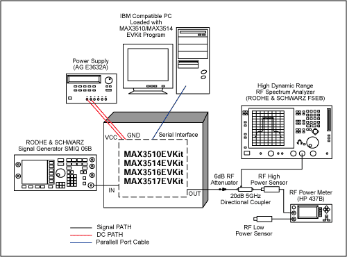 Figure 1. Overall layout of test equipment Test result test signal: modulation factor = 64 QAM α = 0.25 Modulated signal center frequency = 22MHz code rate: 160ksps, 320ksps, 640ksps, 1280ksps, 2560ksps, 5120ksps Table 1. Relationship between the second and third harmonics of MAX3514 and output power and frequency (+ 54dBmV to + 58dBmV)
Table 2. DOCSIS 2.0 specifications for the second and third harmonics (57dBmV output)
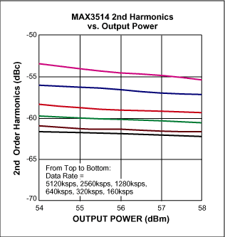 figure 2. 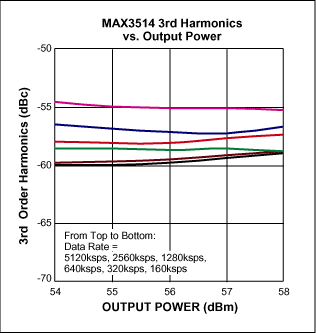 image 3. Table 3. Relationship between the second harmonic of MAX3516 and output power and frequency (+ 57dBmV to + 61dBmV)
Table 4. DOCSIS 2.0 specifications for the second and third harmonics (60dBmV output)
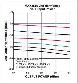 Figure 4. 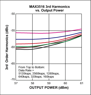 Figure 5. Table 5. Relationship between MAX3514 ACPR and output power and frequency
Table 6. DOCSIS 2.0 specification for adjacent channel power ratio
Table 7. Relationship between MAX3516 ACPR and output power and frequency
Table 8. DOCSIS 2.0 specification for adjacent channel power ratio
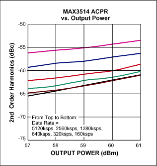 Image 6. 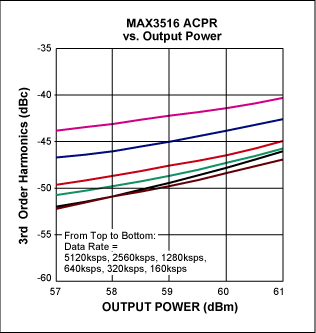 Figure 7. Conclusion The test results of Tables 1, 3, 5, and 7 show that the MAX3514 / MAX3516 comply with the DOCSIS 2.0 standard. |
BURGLARY SAFES
Trusted protection customers` valuables from abnormal entrance to safes in certain conditions such as robberies, personal attacks and so on .
Details:
Our burglary safes are anti-drilling, anti-burglary and anti-force;
Dual-system protection is contained in our safes;
The safes are side door safes with an independently installed board
Burglary Safe,Electronic Burglary Safe,Electronic Digital Safe,Burglar Proof Safe
YONGFA INTELLIGENT TECHNOLOGY SECURITY CO., LTD. , http://www.yongfa-safe.com