The ignition system of automobile engines includes hundreds of electrical and mechanical parts, and the production line is widely distributed. Therefore, the distributed indirect monitoring method is widely used in the monitoring and fault diagnosis system of the ignition system. The engine ignition performance tester analyzes the performance of its distributor and igniter by measuring the engine's closing angle and fire split angle.
The relationship between closing angle, split fire angle and ignition advance angle
Closed angle
Take the gasoline engine four-stroke engine as an example, the piston reciprocates four single-passes to complete a working cycle, and the four strokes include intake, compression, work and exhaust strokes. In one working cycle, the engine camshaft rotates 360 degrees in one revolution.
In the ignition system, the current of the primary winding of the ignition coil from cutoff to conduction and then to cutoff, the cam rotation angle occupied by each cylinder of the multi-cylinder engine is called the closing angle. In a complete working cycle, the primary current undergoes a total of 4 times from cut-off to conduction and then to cut-off, generating 4 ignition pulses, and each of the four cylinders ignites once. As shown in Figure 1, a four-stroke 4-cylinder engine has a duty cycle T of
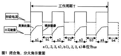
T = (a1 + a2 + a3 + a4 + b1 + b2 + b3 + b4);
In the formula, ai (i = 1, 2, 3, 4) is the i-th conduction time of the primary current in the working period T, and bi (i = 1, 2, 3, 4) is the primary current during the working period T The time of the i-th deadline in
The closing angle α1 of the first cylinder is α1 = a1 × 360 ° / T;
The closing angle α2 of the second cylinder is α2 = a2 × 360 ° / T;
The third cylinder and the fourth cylinder and so on.
If the closing angle is small, the closing time is short, and the primary current growth is less than the required value, it will cause insufficient ignition energy. If the closing angle is too large, for the contact ignition system, it means that the contact gap is small, which will cause arc discharge of the contacts, but weaken the ignition energy, which is not conducive to normal ignition, and the contact closure time is too long, the primary current Continue to energize after increasing to the maximum value, will also make the ignition coil heat. When the closing angles are the same, the time taken for high speed is short, and the time taken for low speed is long. The best case is when the closing angle changes with the speed. Generally, the closing angle of an 8-cylinder machine is 29 ° -32 °, a 6-cylinder machine is 38 ° -42 °, a 4-cylinder machine is 43 ° -47 °, and a 3-cylinder machine is 63 ° -67 °.
Fire angle
Observing the fire angle uniformity is one of the key links in the ignition performance test of automobile engines. Here, the firing angle β1 of 1 cylinder is βl = (al + b1) × 360 ° / T;
The firing angle β2 of 2 cylinders is β2 = (a2 + b2) × 360 ° / T;
The third cylinder and the fourth cylinder and so on.
Ignition advance angle
The gasoline engine sucks the air-fuel mixture in the cylinder and it takes a certain time to burn. In order for the air-fuel mixture to fully burn when the piston reaches top dead center to achieve maximum power, the spark plug should jump before the piston reaches top dead center. The angle of crankshaft rotation from the start of ignition to the time when the piston reaches top dead center is the ignition advance angle. If the ignition is premature, there will be knocking when accelerating, making a sound similar to metal knocking, the piston is blocked upward, the efficiency is reduced, and the wear is increased. If the ignition is too late and the efficiency of gas work is low, the engine is not easy to start, the speed is slow, and the phenomenon of exhaust pipe firing and engine overheating may occur. Therefore, if the ignition is too early or too late, it will affect the speed increase.
The biggest factor affecting the ignition advance angle is the speed. As the speed increases, the time to turn the same angle will become shorter. Therefore, the optimal ignition advance angle can be adjusted according to the engine closing angle and the split fire angle. The purpose of the adjustment is to make the largest part of the gas expansion trend in the piston work power down stroke under various conditions, to achieve the highest efficiency, the smallest vibration, and the lowest temperature rise. Theoretically, the minimum ignition advance angle is 0 °, but in order to prevent the intake air from being ignited during the intake stroke, it is often set to more than 5 °, generally not more than 60 °.
Circuit design
The ignition performance tester includes a power supply module, a measurement and control module, a display module, etc., and its circuit block diagram is shown in FIG. 2. 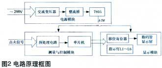
The power module converts 220V AC power into 5V DC power and provides it to other modules. After the measurement and control module collects and limits the ignition signal, it inputs the single-chip 89C52 to measure and calculate the closing angle and the firing angle. The angle value obtained is sent to the display module, and the angle value is displayed in sequence according to the ignition order of the cylinder.
Measurement and control module design
The function of the measurement and control module is mainly realized by the preprocessing circuit and the single-chip computer, as shown in Figure 3. The pre-processing circuit performs amplitude limiting and shaping processing on the input ignition signal to suppress the interference signal, especially the overvoltage or negative voltage that may be generated. Limiting and shaping are mainly completed by the integrated chip LM324 of the operational amplifier combined with the on-off characteristics of the diode. The square wave signal output by the LM324 passes through the inverter 74LS14, and outputs two signals that are inverse to each other. Among them, the inverted signal of the ignition signal is connected to pins P1.0 and INT0 of 89C52, and the other is connected to P1.1 And INT1.
89C52 MCU is the core chip of measurement and control module. The frequency of the ignition cycle signal in the test is low, so the work of the counter is controlled by the logic of the signal. When the signal input terminal is at a high level, it counts, and when it is at a low level, it stops counting. The control bits TR0 and GATE are set to 1 by software, and the working mode of counter 0 is selected as mode 1, whether TH0 + TL0 counts depends on the signal of the INT0 pin. When INT0 changes from 0 to 1, it starts counting, and INT0 changes from 1 When it becomes 0, stop counting. During the counting process, the level of the P1.0 signal of the I / O port is tested by query. When the level is high, the counter automatically counts; when the test reaches a low level, it indicates that the count is over, and the single-chip microcomputer can take the count value and calculate the count result. In this way, the high-level pulse width of the INT0 terminal signal can be counted by the counter 0. This design method effectively guarantees the speed and accuracy of counting. Similarly, the low-level pulse width of the INT1 terminal signal can be counted by the counter 1. The count values ​​of the counters 0 and 1 are calculated by the software to obtain the ignition closing angle and the firing angle. The data corresponding to the angle value is serially output and sent to the LED display module for display. In addition, P1.0 and P1.1 are used to query the status of counting. If the status of port P1.0 changes to "0", it indicates that the counting of counter 0 is completed. At this time, the count value of counter 0 can be obtained. The work of P1.1 and counter 1 is the same. Because P1.0 and P1.1 test is an inverted signal, you can get two half-wave count values ​​of a periodic signal. After processing, the corresponding angle value can be calculated. There is no delay error or interruption error using interruption. 
The keyboard input man-machine interface S1 and S2 are designed in the circuit. S1 is the input function key, and S2 is the system start key. S1 has two functions: car cylinder number selection function and cylinder number reset function. Button S1 is connected to P1.2 of 89C52, and each press increases the number of cylinders by 1. After selecting the number of cylinders, press the test button S2 connected to P1.3 to start the test. In order to reduce the design of the button, in any state, as long as you press the S1 button, you can immediately return to the initial state. The cylinder number selection step re-selects the cylinder number.
Display module design
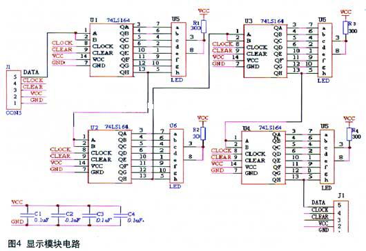
In actual measurement, because the angle value is in degrees, it will not exceed one hundred digits, and it is accurate to tenths, so 4 digital LEDs can be used to display the ignition closing angle of a cylinder. After cascading, it can display multiple channels. The ignition closing angle of the cylinder. This system adopts serial working mode and uses 4-way LED digital tube for display.
The 89C52 data is serially input to the display module. Both the shift clock CLOCK and the clear signal CLEAR are controlled by software. The display module uses a TTL unidirectional 8-bit shift register, which can realize serial input and parallel output, and directly drive a common cathode eight-segment LED digital tube. In addition, using the three I / O pins of 89C52 to connect LEDs L4 to L6 to display the status when working. When L4 is lit, it indicates that the closed angle is currently being displayed, and when L5 is lit, it indicates that the fire angle is currently being displayed. When the number of cylinders tested is greater than 4 cylinders, L6 will light up as a reminder, as shown in Figure 4.
During initialization, press S1, LED digital tube to display the number of cylinders to be tested. Press S2 to enter the working state. Take the 4-cylinder engine as an example. In each round of display, the 4-way LED display module first displays the angle of the 4-cylinder closing angle at the same time. At the same time, L4 lights up and changes to L5 after 3 seconds. Lit, the LED board shows the angle of the fire angle. In order to improve the utilization rate of the seven-segment digital tube, this design adopts the method of turning the page display of the angle value for the engine with more cylinders. For example, the 8-cylinder engine can still only use the 4-way LED display module. The first round displays only the angle value of the first 4 cylinders, and the second round displays the angle value of the rear 4 cylinders. When the angle of the rear 4 cylinders is displayed, L6 Will light up as a reminder.
software design
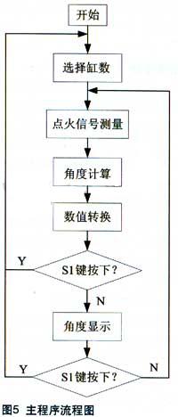
After a certain preprocessing, the ignition signal is sent to the 89C52 single-chip microcomputer to complete the measurement, calculation and corresponding display. The software flowchart of the main program is shown in Figure 5. The software design mainly includes modules such as cylinder number selection, counter counting measurement, interrupt service, angle calculation and display.
Program design of cylinder number selection module
The panel of the tester is provided with a cylinder number selection button S1. Each time the button is pressed, the cylinder number is increased by 1. After selecting the number of cylinders, press button S2 to start the test. In addition, there are many places to query the button S2 in the program. If you want to re-select the number of cylinders during the working process of the tester, you can press S2 at any time without releasing it. It will be queried and the program will re-enter Number of cylinders selection stage.
Counter counting and interrupt service program design
When the rotation speed exceeds the range calibrated by the tester, the counter 0 or 1 overflow interrupt will be generated. At this time, the LED displays "E", which means "ERROR". Just adjust the rotation speed in real time to re-enter the counting program and start the measurement.
Angle display programming
After calculating the angle value of the closing angle or the fire angle, the binary value of the angle value is converted into a BCD code by the decoding program and temporarily stored in the accumulator. The accumulator serially transmits the angle data to 74LS164, and then sends it to the eight segment The digital tube displays the decimal angle value of the current BCD code.
Conclusion
This article completes the hardware and software development of the 89C52-based automotive ignition performance tester in the SUPERIMAGE-3000 development environment. The experimental data and loading test results are stable and reliable, and the accuracy meets the standards. The index is of great significance for adjusting the efficient ignition timing and ignition advance angle.
custom logo:please send me your logo,and we will printed them on the credit Card USB Flash Drive which is a good idea of your company to do promotion gifts,This item is very popular.
The best gifts for company promotion/Wedding gift,you can not miss this card usb in such situation.
Selling Point:
1.We promise all USB Flash Drive is real full capacity.
2.The chip 100% test before production.
3.Free design for custom logo.
4.Free sample for small capacity ,just pay for the shipping cost.
USB Flash Drive Card,Card USB Flash Drive,USB Business Card,USB Pen Drive
Custom Usb Gift company limited , https://www.customusbgift.com