Challenges for assisted driving system development Automotive assisted driving (DA) system engineers often use PC models to create complex processing algorithms in order to achieve highly reliable adaptive cruise control, lane departure warning, and pedestrian detection. Developers attach great importance to the PC algorithm model because this model allows them to try and quickly evaluate different processing algorithms. However, in the final analysis, a properly designed electronic hardware solution is still needed to achieve cost-effective mass production and deployment.
Verifying the consistency of algorithm performance between deployable target hardware and software algorithm models is a problem for many developers. Moving from floating-point to fixed-point calculations (such as the different methods used by trigonometric functions) sometimes results in significant differences between the reference software algorithm and the hardware implementation model. In addition, the input pattern data cluster (input sTImulus) has a lot of uncertainty, which makes the verification algorithm performance consistency work more complicated.
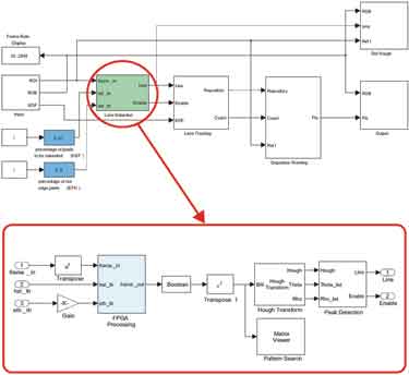
Figure 1 LDW top-level block diagram
For DA systems that usually rely on input from remote sensing devices (cameras, radar, etc.), the input information is the various road conditions and environmental conditions that the driver may encounter in actual driving. Engineers will find it challenging to design a processing algorithm that fully meets the needs of all situations, and it is critical to verify the consistency of algorithm performance between the software model and the implementation of electronic hardware.
A tool from Xilinx, System Generator for DSP, provides an efficient and intuitive method for algorithm developers and system architects to move from Simulink PC models to real-time FPGA hardware implementation technology. This design tool with a high level of abstraction has played a key role in the design project jointly undertaken by Xilinx and eVS engineers. The goal of the project is to use the System Generator for DSP to introduce a graphics processing algorithm suitable for vehicle lane departure warning systems using Xilinx FPGAs, aimed at improving overall performance, reducing costs, and shortening development time.
Lane departure warning model The overall function of the lane departure warning (LDW) system is to alert the driver when the vehicle inadvertently deviates from the driving lane. A camera is placed in front of the vehicle where the system is installed, and road conditions can be captured to identify lane boundary signs. The lane departure warning system continuously tracks the lane markings and the position of the vehicle relative to the lane markings. If the vehicle crosses the lane marking, the system will issue a warning.
The automotive industry and academia generally use MATLAB and Simulink as algorithm and system-level design tools. Especially Simulink has a high abstraction layer and provides graphical input, so it can help automotive algorithm engineers to develop complex DSP algorithms easily and quickly.
Figure 1 shows the top-level block diagram of the LDW system model, which is designed using Simulink. The green block marked for lane detection includes the graphics pre-processing subsystem, and the processing steps of this subsystem are given in Figure 2. The lane detection function aims to extract the most likely road condition graph representing the lane markings.
In order to improve the performance of edge device noise detection, the first step of the processing pipeline (pipeline) is 2-D 5 × 5 Gaussian noise suppression (GNR); the second step is histogram widening (HST), developers can use this technology to enhance graphics contrast Use the entire gray scale range as much as possible; the third step is the horizontal / vertical gradient (HVG), which can enhance the pixels when the local intensity changes greatly. Developers can perform HVG by calculating the 2-D 5 × 5 gradient of the graph.
System Generator tool overview
The System Generator for DSP design tool runs in Simulink. It uses Xilinx's DSP module set for Simulink, and will automatically call the Xilinx CORE Generator tool to generate a highly optimized DSP building block netlist, which can be accessed through the Simulink library browser. The library browser can be launched from the standard MATLAB toolbar. There are more than 90 DSP building blocks available for building a DSP system. It also includes FIR filters, FETs, FEC cores, embedded processing cores, memory, arithmetic blocks, logic blocks, and bit-wise blocks. Each block achieves cycle accuracy and bit accuracy, and it can be individually configured for delay, area and speed performance optimization, I / O port number, quantization, and rounding.
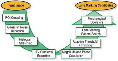
Figure 2 Below the LDW preprocessing function chain, let's take a closer look at how to build a graphics processing algorithm model in the System Generator for DSP. For simplicity, we choose GNR as an example, which is also the first module of the graphics preprocessing process.
The random variation of the intensity value (ie noise) of the GNR function implemented by the System Generator usually damages the image quality. This change appears as a Gaussian or normal distribution and is more common in different sensors (ie CMOS cameras). Linear smoothing filters are the best way to eliminate Gaussian noise. In many cases, it can also eliminate other types of noise. To achieve this function, a linear finite impulse response (FIR) filter can be implemented by using a weighted sum of pixels in a continuous window.
Before starting to implement the GNR System Generator module, we have implemented its behavior model in MATLAB. This can be achieved with only two lines of code. First, the kernel needs to be calculated, and the mask size (in this case set to 5 × 5) and Gaussian ∑ value are described in detail. Then, the input image can be filtered by convolution.
n_mask = fspecial ('gaussian', 5, 0.8);
out_img = conv2 (in_img, n_mask, 'same');
In addition, you can use this behavior model and test the filter with actual video data to adjust the mask coefficients. You can also verify that the output of the System Generator for DSP subsystem is equal to the output of the MATLAB function (within the specified error range, this is because MATLAB works in floating point mode, while System Generator works in fixed point algorithm mode) to Verify the hardware.
The 2-D GNR module processes the input image in a streamlined manner (ie, progressively). Figure 3 shows the top-level block diagram of the System Generator and the Gaussian noise suppression function of the entire pre-processing chain.
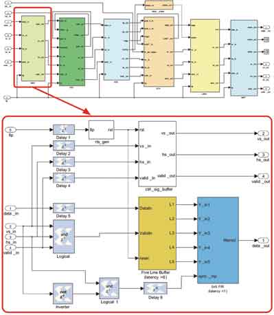
Figure 3 Block diagram of top-level preprocessing and Gaussian noise suppression
System Generator FPGA synthesis results Developers must design at a cost level suitable for mass production when developing driver assistance systems.
The die resources required to achieve a certain processing performance will determine the size of the FPGA device they need, and thus their cost.
In implementing the lane departure warning preprocessor, the XA Spartan-3A DSP 3400 was targeted. Use this method and use the model to support development activities in future planning. However, analysis of the resources taken up by the preprocessing function shows that the design is suitable for much smaller devices.
Table 1 shows the resource occupancy of the GNR block on the XA Spartan-3A DSP 3400 device. In the calculation, it is assumed that the frame rate of the grayscale input image is 30 Hz (that is, the input data rate is 9.2 MS / s) at VGA resolution.
From a timing performance perspective, the GNR design operates at a clock frequency of 168.32 MHz and can accept input data with a data transfer rate of up to 18.72 MS / s.
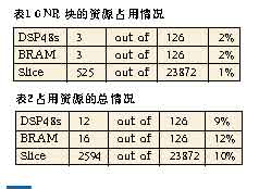
The total resource requirements of the entire lane detection pre-processing subsystem are shown in Table 2.
The corresponding timing performance analysis shows that the clock frequency is 128.24MHz and the highest input data transmission rate is 14.2MS / s.
According to the analysis of the above required resources, the pre-processing function can even be used for the XA Spartan-3E 500, whose density is about 1/7 of the XA Spartan-3A 3400A device.
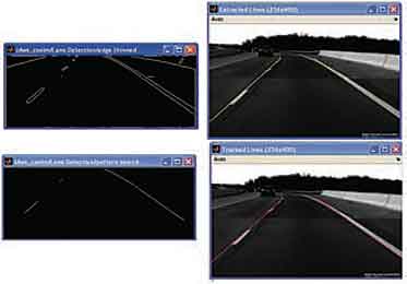
Figure 4 LDW processing model output
Results Figure 4 shows the performance pattern of an LDW system, including FPGA-based image preprocessing functions for lane line backup extraction. As you can see, the input frames in the two pictures on the right. The pair of images on the left show the performance of the preprocessing function we implemented in the FPGA. The picture in the upper left corner shows the amplitude of the edge detection function after thresholding. The picture in the lower left corner was taken after thinning the edges and searching for the lane pattern. Obviously, the LDW preprocessor can take road pictures very efficiently, and can reduce the data to the basic lane line selection. The yellow and red lines in the upper right and lower right pictures represent the instantaneous tracking calculation results of the lane marking based on the simple straight road model, respectively.
Side View Camera,Rear View Camera,Camera Parking,Camera Reverse
Shenzhen Sunveytech Co.,LTD , https://www.sunveytech.com