1 Introduction The steering performance of a vehicle directly affects the vehicle's mobility, handling stability, and economy of use. Multi-axle steering technology improves the flexibility and maneuverability of the car when turning at low speeds, and improves the handling stability of the car at medium and high speeds by changing the turning angle of the other axles. By changing the over-steer or under-steer that appears in the car instantaneously, the dynamic stability of the car is enhanced, the car is made safer, and the car is prevented from running out of control due to over-steer or under-steer.
2 The realization principle of multi-axis steering system The steering control mode of multi-axis steering system can be divided into mechanical type, hydraulic type and electronic type according to its structure and actuator. At present, multi-axis steering devices have closely combined mechanical, hydraulic, electronic, sensor and microprocessor control technologies. The electronic control part of a three-axle all-terrain crane multi-axle steering system is studied. Because of the strong real-time performance of the system, the more popular CAN bus control method is adopted. This paper designs a part of the electronic control system of a high-performance automobile electric steering gear.
3 Hardware design of electric control system Multi-axis steering system based on CAN bus adopts modular design, mainly composed of main control module and drive control module. The main control module calculates the rotation angle value of each rear axle according to the vehicle's driving attitude and the multi-axis steering control strategy (using the zero-side slip proportional control strategy); the drive control module is responsible for controlling the steering execution process. The electronic control unit of the multi-axis steering master control module processes and calculates the front wheel angle signal and vehicle speed signal collected by the sensor through a predetermined control strategy to obtain the optimal rear axle angle value, and at the same time sends each axle angle value to the bus. The electric control unit of the control execution module, after identifying and receiving the respective data, converts the rotation angle value through the PID control to drive the proportional solenoid valve PWM voltage signal, controls the position of the hydraulic cylinder piston, and at the same time uses the displacement sensor to convert the real-time hydraulic cylinder displacement value The feedback to the electronic control unit makes the rotation angle of the rear axle have a certain accuracy, so as to achieve the purpose of multi-axis steering.
3.1 General overview of the multi-axis steering electronic control system The multi-axis steering electronic control system designed in this paper is mainly composed of two modules, and each module is composed of three parts: sensor, electronic control unit (ECU) and actuator. Its design mainly includes the selection of sensors and controllers, the design of the signal acquisition system and its processing circuit, the design of the CAN control and receiving circuit, the actuator and its driving circuit. The hardware block diagram of the multi-axis steering electronic control system based on CAN bus is shown in Figure 1. 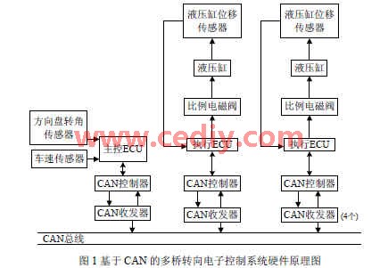
3.2 Selection of sensors
(1) Vehicle speed sensor Hall vehicle speed sensor is a magnetoelectric sensor based on Hall effect, which has the characteristics of high sensitivity to magnetic field, stable output signal, high frequency response, strong anti-electromagnetic interference ability, simple structure, convenient use, etc. Thus it is widely used. Its structure is mainly composed of ring gear, Hall element, permanent magnet and electronic circuit. The principle is shown in Figure 2: 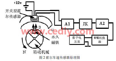
(2) In the multi-axis steering control system of the steering wheel angle sensor, the front wheel angle is required as a control parameter. Because the front wheel angle value is difficult to obtain, the steering wheel angle value is measured and the front wheel angle value is obtained by calculation.
(3) In the multi-axis steering control system of the hydraulic cylinder displacement sensor, it is necessary to obtain the value of the rear wheel rotation angle to determine whether the steering is in place.Because it is difficult to directly measure the rear wheel rotation angle, and the position of the hydraulic cylinder corresponds to the rear wheel rotation angle, we passed The displacement of the hydraulic cylinder is measured to indirectly measure the rotation angle of the rear wheel, and at the same time, the rotation angle value is fed back to the ECU. This article uses a variable resistance displacement sensor. In terms of the selection of microprocessors, we strive to absorb the valuable experience of mature products at home and abroad. After conducting a wide range of electronic product market research, on the basis of comprehensive cost performance, this system selected 8-bit P89C52 series microcontrollers produced by PHLIPS as the system microprocessor.
3.3 Hardware circuit design of CAN bus system node The design of CAN bus node in the multi-axis steering electronic control system based on CAN bus is particularly important. The CAN bus node system designed in this paper uses P89C52 as the microprocessor. In the CAN communication interface, the CAN communication controller SJA1000 and the CAN bus driver use 82C250. The circuit is mainly composed of four parts: microcontroller P89C52, independent CAN communication controller, SJA1000CAN bus transceiver 82C250 and high-speed photocoupler 6N137. Microprocessor P89C52 is responsible for the initialization of SJA1000, and realizes communication tasks such as data receiving and sending by controlling SJA1000. 4 Signal acquisition hardware circuit design
4.1 Vehicle speed signal conditioning circuit The multi-axis steering control system needs to detect the vehicle speed value in real time. The detection of the vehicle speed value is a Hall speed sensor that converts the speed of the transmission output shaft into a sequence pulse of different frequency. The single-chip computer counts the pulse sequence and converts it into the current Speed ​​value. Generally, the pulse signal generated by the sensor is relatively weak, and it needs to be processed into a TTL or CMOS signal input single-chip microcomputer through the amplifier circuit. However, most of the vehicle sensors have signal processing circuits, and the output voltage is the vehicle voltage range, which must be adjusted before they can be input into the single-chip microcomputer. In addition, the rectangular pulses obtained from the sensor are often distorted after transmission. By using the positive feedback function in the state transition process of Schmitt trigger, the periodic signal with slow edge change can be transformed into a rectangular pulse signal with very steep edge. The vehicle speed signal conditioning circuit designed based on the above principles is shown in Figure 3. 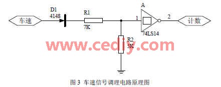
4.2 Front wheel rotation angle signal conditioning circuit According to the working principle of the rotary encoder, when the steering wheel rotation angle changes, the photoelectric encoder will send out a digital pulse signal with phase difference of 90 ° between A and B. A leads B by 90 ° in forward rotation, and B leads A by 90 ° in reverse rotation. The number of pulses is proportional to the angle value, so you can get the size of the steering wheel angle by counting the pulses. Considering that the car steering wheel rotates in both directions, it can be rotated clockwise or counterclockwise, and the output signal of the encoder needs to be phase-detected before counting. 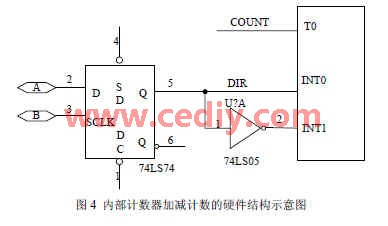
We can connect the pulse after the D flip-flop, that is, the direction control pulse (DIR), to the external interrupt INT0 terminal of the microcontroller, and then to another external interrupt INT1 after the inverter, and connect the count pulse A to the chip of the microcontroller. The internal counter T0 can be used. Compared with the external counting chip, the circuit is relatively simple when using this method. When the system works, first set the two interrupts to low level trigger, and open the corresponding interrupt. When DIR is high, it means that the steering wheel rotates clockwise, INT1 is interrupted, and the corresponding interrupt program is executed to perform up counting; while when DIR is low, it means that the steering wheel is rotated counterclockwise, INT0 is interrupted, and the corresponding interrupt program is executed, and the count down (Actually it is reassignment, up counting). Figure 4 is a schematic diagram of the hardware structure of the internal counter up and down counting.
4. 3 Hydraulic cylinder displacement signal conditioning circuit The electronic control system needs to detect the current value of the rear wheel rotation angle at all times and compare it with the target rotation angle value to obtain the deviation e (t) and generate a PWM signal until the deviation e (t) is within the allowable range Inside. The measurement of the rear wheel angle is obtained indirectly by measuring the displacement value of the hydraulic cylinder. The displacement signal is an analog signal. There is no A / D conversion module in the P89C52 MCU, and an external A / D conversion circuit is required. Adopt 8-bit AD678 to complete. The advantage of AD678 is that the polarity of its analog signal input is very easy to control, and the pin connection is simple.
4.4 Driver execution hardware circuit design
4.4.1 The proportional solenoid valve drive circuit usually has a maximum switch voltage signal of 5V output from the microcontroller, and according to the electrical performance of the MCS-51 series chip output, its output current should not exceed 15mA, which is insufficient to drive the proportional valve electromagnet. Therefore, it is necessary to have a driving power amplifier to amplify the switching voltage signal, so that sufficient excitation current is generated in the electromagnetic coil. For the proportional directional valve, in order to speed up the current response speed of the electromagnetic coil, a fast drive circuit must be used, that is, a circuit in which the current increases and disappears very quickly. This article uses the VMOS power field effect transistor as shown in Figure 7 to form the power amplifier circuit schematic diagram. The driving power of this circuit is large, the response time is in the millisecond level, and the isolation between the microcontroller and the power level is good. In the circuit diagram 5, the input part and the output part use two sets of independent power supplies, which do not share the ground and have no electrical connection, thus achieving electrical isolation. 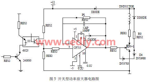
4.5 Other peripheral circuit design
4.5.1 Power supply circuit The power supply module converts the vehicle power supply into the voltage required by the control system through DC / DC conversion. The vehicle power supply is 12V or 24V, and the working voltage of the single-chip system is 5V. There are many kinds of DC / DC converters, this system uses 78L05 of 78L00 series to step down. 78L00 series DC / DC converter circuit is simple and practical, only need to add two capacitors to form a conversion circuit. The input range of 78L05 is 7V-24V, and the output voltage is 5V.
4.5.2 Reset circuit In the general computer system, in order to prevent the system from malfunctioning due to power-on, sudden power failure and instantaneous undervoltage of the power grid, a reliable reset circuit and power monitoring circuit are required.
Innovative points of the author of this articleThis paper proposes the multi-axis steering technology based on CAN bus for the real-time multi-tasking characteristics of the multi-axis steering system to ensure the safety and stability of the vehicle in the steering state and the fast following characteristics of the rear axle steering; Multi-axis steering electronic control unit including main control module and control execution module.
Solar LED land lamp uses sunlight as the energy source, charges during the day and uses at night, does not need complex and expensive pipeline laying, can arbitrarily adjust the layout of lamps and lanterns, safe and energy-saving, pollution-free, stable and reliable without manual operation, saving electricity and maintenance. Solar LED street lamp is mainly composed of solar cell module (including bracket), LED lamp holder, control box (with controller, battery) and lamp pole.
Solar Led Street Light,Street Light Lamp,Solar Powered Street Lights,Solar Powered Led Street Lights
Yangzhou Heli Photoelectric Co., Ltd. , https://www.heli-eee.com