1 Introduction
With the increasing number of controlled nodes and control complexity in the automotive network, in order to meet the control requirements and reduce the development cost of the control system, automotive manufacturers and automotive design units are increasingly demanding embedded automotive software development tools . At present, some software development technologies and software development tools for this application field already exist on the market, such as rapid prototyping-based software design technologies and MATLAB / Simulink, dSPACE development tools. Rapid prototyping-based software design technology refers to a software development method in which software designers describe and describe software functions by creating and maintaining a functional model of embedded software, and use automatic code generation technology for microprocessors to achieve rapid generation of lower-level computer code. Using this technology can improve the efficiency of embedded software development and reduce development costs.
However, current software development tools focus on single electronic control unit (ECU) modeling and verification software's execution efficiency and performance in a single ECU environment; the robustness and feature analysis support for control strategies in network scenarios are limited. On the other hand, network protocol simulation and analysis tools, such as OPNET, can provide protocol performance analysis in network scenarios [6], but because the simulation code developed on OPNET cannot be directly ported to the controller, the development work cannot be conveniently achieved Reuse for target systems.
If we aim at the application scenario of the CAN bus network for vehicles, we will combine the rapid prototype-based embedded software design and the analysis based on network simulation to realize the rapid prototype of the vehicle CAN bus network. In the early stage of the design, the virtual hardware defined by the model is used to replace the actual hardware that has not been designed or the cost of ownership is too high, and the initial system design analysis is performed; when the corresponding hardware is in place, the virtual hardware is replaced and the model code is transformed into the target of the target system Code, verify and analyze closer to the actual system; finally, when all the actual control software, controller hardware and controlled hardware are completed, an integrated real-time simulation of the entire system is performed. This can solve the problems of using independent tools to develop models and perform simulation verification.
In this paper, through the design and implementation of rapid prototyping of CAN bus network for vehicles, a system for design, simulation and performance analysis of CAN bus network for vehicles is provided; The related controller model and controlled object model, as well as the CAN card simulation program TH-CAN-Vcard and CAN bus analysis tool TH-CAN_Scope under the Windows environment, are implemented under the CAN bus network environment for the vehicle CAN bus network scenario Organic combination of control strategy simulation analysis and control code generation.
2 System design and implementation
2.1 Analysis of characteristics of CAN bus network for vehicles
The CAN bus is a serial communication bus. Carrier sense multiple access with collision detection (ie CSMA / CD) for bus arbitration and control. In order to standardize the performance of the CAN bus for vehicles in network scenarios, the International Organization for Standardization ISO and the American Society of Automotive Engineers SAE have formulated relevant international standards for the reference environment of CAN communication diagnosis. These standards define the benchmark test requirements from different levels based on the layered structure of the CAN protocol. For example: SAE J2012 and ISO / DIS 15031-6 correspond to the definition of fault diagnosis at the application layer; [3] [7] ISO / DIS15765-2 corresponds to the network layer communication protocol, which provides long Message data segmentation / reassembly, data transmission with flow control, and message timeout processing control between the on-board control unit and the off-board test tool. [2]
On the other hand, various automobile manufacturers have also formulated their own corporate standards based on these international standards to regulate the products of ECU product suppliers. For example, the DaimlerChrysler-Benz Group's CAN communication standard software model is divided into two parts: vehicle diagnosis related modules and vehicle diagnosis independent modules. Among them, the modules related to vehicle diagnosis are divided into diagnostic protocol services (KWP2000) and network transmission protocol services (ISO-15765-2), which correspond to the functional descriptions of application layer services and network layer services, and define relevant benchmark environmental parameters and test messages. sequence. [2]
These standards provide detailed definitions of the content of CAN-based diagnostic services in the automotive environment, the logical relationship between network transmission message sequences, and delay requirements. According to these requirements, providing a CAN bus network rapid prototype, truly simulating the message sequence and data stream with the given characteristics, and reproducing the possible interference and error signals are the core technical work of this design. The results of this work can provide an analysis of the relationship between network traffic, network efficiency, and network response, and simulate and verify the robustness and real-time nature of ECU control codes in a CAN network environment for vehicles.
2.2 Structure and implementation of rapid prototyping system
This rapid prototyping system has three types of nodes: an actual CAN node with a physical CAN hardware interface, a virtual CAN node composed of TH-CAN-Vcard and Simulink models, and a monitoring node running the TH-CAN-Scope analysis tool. When designing simulation experiments, the number of nodes is not limited, and is only affected by the addressing scheme of the specific CAN application layer. The first type of node is the CAN node we usually use. Here we focus on the realization of the latter two types of nodes.
2.2.1 Virtual CAN node
The virtual CAN node is composed of TH-CAN-Vcard and Simulink model. The node implementation is shown in Figure 1. When the physical CAN card does not exist, using virtual hardware technology, by selecting the virtual CAN channel provided by the CAN card driver library, and instantiating the developed VCANCtrl control object into a COM server (COM Server), you can establish a COM server and MATLAB under a single machine The connection between the model (as a COM client). The process of virtual receiving / transmitting CAN messages to the CAN bus provides basic CAN communication test functions for the models established under Simulink. When the physical CAN card exists, you can directly modify the target CAN channel in the model, so that the model in MATLAB has the function of communicating with other physical CAN nodes. At this time, multiple models located on different PCs and multiple ECU hardware The controller code above can establish a CAN network simulation analysis environment for the vehicle via the CAN bus.
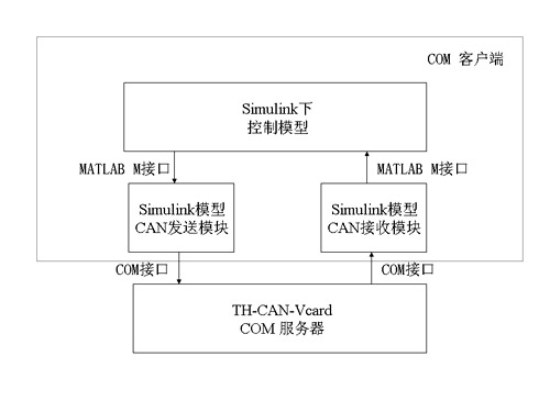
Figure 1 Implementation of virtual CAN node
TH-CAN-Vcard is a CAN card emulation program developed under the Windows environment using Visual Studio .NET and KVASER's CAN card driver library. We developed the VCANCtrl control object through AcTIveX technology, and implemented the following internal functions in VCANCtrl:
VCAN_Read message receiving function; the entry parameter is the CAN channel handle, and the return parameter is the ID, data packet, length, identification and time stamp of the CAN message in the receive buffer.
VCAN_Write message sending function; the entrance parameter is the CAN channel handle, and the ID, data packet, length and identification of the CAN message to be sent.
VCAN_Start CAN card initialization function; entry parameters are selected CAN channel number, baud rate, channel opening mode, synchronization mode and synchronization segment, and CAN controller working mode.
VCAN_Close CAN card close function; the entry parameter is the handle returned when the CAN card is initialized successfully.
2.2.2 Monitoring node
The monitoring node is a node that monitors and controls the CAN bus message sequence, and runs the TH-CAN-Scope-CAN message simulation analysis tool. TH-CAN-Scope is a tool for simulating CAN message sequence and recording and analysis of simulation results. It is an application under Windows developed using KVASER's CANLIB SDK.
TH-CAN-Scope's CAN message processing functions include: creating / editing message flow sequences, CAN communication management, CAN message sequence tracking, console man-machine interface, and database maintenance for message sequence management. Among them, creating / editing message flow sequences, CAN message sequence tracking, console man-machine interface, and message sequence management related to database operations use user threads. However, CAN communication management requires high real-time performance, and uses independent worker threads. The two threads communicate with each other by using the message processing mechanism under Windows.
In addition, the analysis functions provided by TH-CAN-Scope include: online display of CAN messages, online statistics of CAN bus usage, recording of CAN messages on the bus, and active / cyclic transmission of CAN disturbance messages. And record CAN messages collected in a period of time in the database, you can perform more detailed and in-depth performance analysis, by using the CAN message editing tool, you can specify the monitoring node to trigger at a time (send a certain Group CAN message) and event trigger (send a specified CAN message sequence when a CAN message is received or a certain type of CAN message is received) mechanism to send a trigger message to examine the performance of the CAN bus.
2.3 System implementation technology
2.3.1 Implementation of MATLAB external program interface
TH-CAN-Vcard provides the function of CAN communication for the controller model and controlled model under MATLAB, and adopts COM technology. Compared with the Matlab external communication method implemented with DDE technology [4], the performance of COM technology is better. In the test done by Emanuele Ruffaldi et al., COM compared with DDE, write performance increased by 10 times, read performance improved More than 30 times [5]; In addition, MATHWORKS does not continue to develop the DDE interface, and it is recommended to use the COM interface.
For specific use, first we construct the VCAN sending module and VCAN receiving module in Simulink, use the actxcontrol command in M ​​language to instantiate the VCANCtrl COM object to obtain its handle, and then we can call the corresponding object in the COM object through this instantiated handle The VCAN_Write and VCAN_Read functions realize the CAN communication support of the control model in Matlab, which is equivalent to a handle device in use.
2.3.2 Realization of data flow simulation and node synchronization
In order to generate the specified CAN message sequence on the CAN bus, we define the required message sequence through TH-CAN-Scope, and then define the response operation to the CAN message on the bus through a combination of time triggering and event triggering, and The corresponding control logic is realized through the Simulink model. Therefore, the actual control strategy is similar to that distributed in each CAN node. Synchronization between nodes means that all CAN nodes on the bus should be able to generate their designated message sequences at a time. Using TH-CAN-Scope broadcast to send custom CAN synchronous transmission messages and start the timer of each node, you can achieve node synchronization with a certain accuracy.
2.3.3 Implementation of CAN bus performance analysis
In the performance analysis of the CAN bus, we implemented the following analysis functions: examine the impact of bus load (including the number of nodes, the amount of information of each node, and the bus rate set by each node); examine the impact of node priority strategies; and investigate fault tolerance The impact of strategies (for example, nodes with a high transmission and reception error rate should actively quit the CAN bus network); and investigate the real-time performance of the CAN network, mainly including the range of network message message delays and changes in message message delays. Among them, the size of the delay describes the static characteristics of the packet delay, and the change of the delay describes the dynamic characteristics of the packet delay.
3 System function test and analysis
In order to verify the rapid prototyping system's support for mixed simulation of virtual hardware and actual hardware under multiple ECUs, we designed the system function test experimental platform shown in Figure 2: where ECU-A and ECU-B are two independent hardware ECUs. The TH-ECU2003 controller developed in the laboratory; ECU-C and ECU-D are two independent control models developed in Simulink. The software emulation CAN card function is realized by the VCAN sending module and the VCAN receiving module, which is virtual hardware. In the test, by filtering the received CAN messages at each node, the control communication flow is shown in Figure 2, ie ECU-A-> ECU-B-> ECU-C-> ECD-D-> ECU-A. In order to verify all scenarios under mixed simulation of virtual hardware and actual hardware.

Figure 2 Experimental platform for rapid prototyping system functional testing
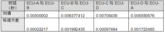
In the experiment, using TH-CAN-Scope as the monitoring software, the data on the CAN bus was collected for 5s, and the average time delay and standard deviation of more than 2000 CAN message messages between nodes were analyzed (the time The delay includes the processing delay of the node and the transmission delay between the nodes). The analysis results are shown in Table 1. Experiments prove that any two nodes in the system can communicate normally, meet the test requirements, and verify the effectiveness of the system design. .
Table 1 Delay analysis of CAN message in experiment
4 Conclusion
This paper designs and implements a rapid prototyping system for the CAN bus network of vehicles to solve the problem that existing ECU software development tools focus on single ECU modeling and the development code in existing network simulation tools is difficult to reuse on the target system. Finally, the effectiveness of rapid prototyping system design is verified by a simulation environment composed of THECU-2003 hardware platform and Simulink control model.
A number of different industries commonly use Led Neon Light Signs – shop, store, home, hotels, bar, restaurant and more. We offer a long-lasting and economical solution for any of your professional, and even personal, Neon Signage needs. Our custom neon sign boards provide both a functional, art and aesthetic purpose. Whether indoors or outdoors, these illuminated neon signs help establish a high-end impression for your business.
Led Neon Light Signs,Outdoor Led Open Sign,Led Sign Boards,Outside Neon Lights
Shenzhen Oleda Technology Co.,Ltd , https://www.baiyangsign.com