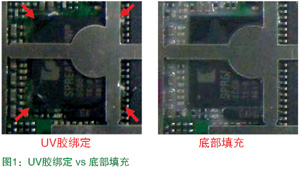
An important factor affecting the quality of mobile phones is the reliability of chip solder joints on mobile phone motherboards. In order to improve the reliability of chip solder joints, many well-known companies have adopted the underfill process; and the UV glue bonding process that has matured in the notebook computer manufacturing industry has not yet been widely applied in the mobile phone field.
This article refers to the address: http://
This paper mainly discusses the effect of non-dispensing, UV bonding and underfill on the solder joint reliability of mobile phone motherboard chips under the lead-free process (using the roller drop test for reliability verification and slicing test). At the same time, the related process and reliability of the UV glue binding of the mobile phone chip corner are discussed.
The experimental design randomly selects 6 mobile phone motherboards for one batch of the same product, and implements three process flows: 2 without dispensing or underfilling, 2 for bottom filling of the main chip, and 2 for UV to the four corners of the main chip. Glue binding, as shown in Table 1:

The verification process refers to the standard GB2423.8, and the roller fall tester is used for reliability verification. The specific process is as follows: 1. Ensure that the selected board passes the AOI, visual inspection, X-Ray inspection, and passes all functional tests; 2. The selected 6 Block motherboard: 2 pieces do not make glue; 2 pieces do bottom filling; 2 pieces do UV glue edge binding, test after drying and solidification; 3. Simulate mobile phone assembly and fixing method to make the main board's drop fixture; 4. According to the test Experience the selection of a roller with a height of 1,000mm for the drop test; 5. Perform a full-featured test for every 100 drops until a problem occurs; 6. Perform a failure analysis on the defective motherboard.
Test results The actual drum drop test results are shown in Figure 2.
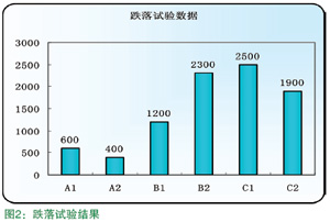
After the motherboard fell test results: 6 drop test prototype motherboard failure information is unable to boot.
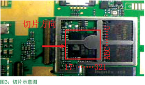
Failure Analysis After the test technician analyzed the failed motherboard, it was confirmed that the main chip or the flash memory failed to boot. The failure location is sliced ​​(see Figure 3) and the results are as follows:
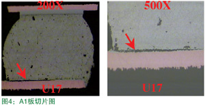
After the A1 board is sliced, the main chip solder joint U17 has a crack at the solder joint of the pad and the solder ball, as shown in FIG.
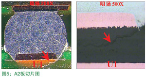
After the A2 board is sliced, the main chip solder joint U1 appears to be partially cracked at the PCB side pad, as shown in FIG.
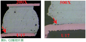
After the B1 board is sliced, the main chip solder joint A17 has cracking under the PCB pad, as shown in Fig. 6.

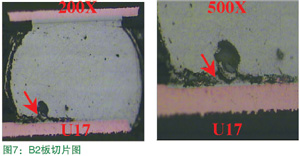
After the B2 board is sliced, the main chip solder joint U17 has a crack between the PCB pad and the solder ball, as shown in FIG.
After the C1 board is sliced, the main chip solder joint U1 has a crack between the PCB pad and the solder ball, as shown in FIG.
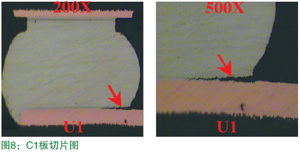
After the C1 board is sliced, the main chip solder joint U1 has a crack between the PCB pad and the solder ball, as shown in FIG.
Rework process comparison compares the repair condition and process cost of the underfill and UV glue-bonded mobile phone motherboards (see Table 2). The UV glue-bonded chips are easy to repair and are not scrapped.
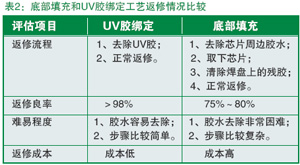
The comprehensive glue, labor, equipment, process and other aspects are roughly estimated, and the cost of rework of the underfill process is more than twice that of the UV glue bonding method.
The summary can be known from the above test data comparison and failure analysis:
1. The most vulnerable part of the chip of the mobile phone motherboard is the solder joints of the four corners;
2, using UV glue binding or underfill technology, the board's anti-fall reliability is more than twice the product without using these two processes;
3, the bottom filling process on the solder joint protection and product reliability is slightly better than the UV glue binding process, but the UV glue binding in the practical application is operability, easy to repair and cost less than 50%;
4. These two different methods of enhancing reliability allow the designer to select the appropriate process as needed.
Organic Light Emitting Display
Oled Display Module,Segment Led Display Module,Bendable Oled Flexible Displays,Tow-Color Oled Display Modules,OLED
ESEN Optoelectronics Technology Co., Ltd, , https://www.esenoptoelectronics.com