CyFi-based wireless sensor network formation and communication design
Relevant protocols for implementing wireless sensor networks are emerging, such as infrared, Bluetooth, ZigBee, Wi-Fi, etc. However, there are various problems with these protocols, for example, infrared technology fails when it encounters obstacles, Bluetooth consumes more power, and the ZigBee protocol is more complicated. In response to these problems, Cypress launched the CyFi low-power wireless solution, and also introduced the PSoC FirstTouch starter kit CY3271 for novices and other expansion kits. This article uses this kit to build a CyFi wireless sensor network, and realizes the binding and data collection of nodes on the PC through the USB interface.
1 Introduction to CyFi
The WirelessUSB technology previously introduced by Cypress has been widely used in wireless mice, keyboards, gamepads and other products. On this basis, Cypress has launched a low-cost, low-power, high-reliability wireless radio frequency solution for embedded control-CyFi. CyFi's market positioning makes it reliable, simplified, low-power, and multi-channel.
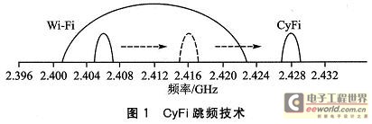
â‘ Reliable. By using Direct Sequence Spread Spectrum (DSSS) modulation technology, CyFi can recover transmitted data from possible errors, thereby providing excellent connection reliability. For interference from Wi-Fi, Bluetooth, ZigBee and other wireless technologies that also work in the very crowded 2.4 GHz band, CyFi's frequency hopping technology can automatically search for clean channels at predetermined frequency band intervals for communication, as shown in the figure 1 shown. At the same time, CyFi's link management function can automatically adjust the transmission power and transmission rate to the optimal configuration to ensure reliable links according to the network environment. DSSS modulation, frequency hopping technology and mature link management algorithms make CyFi a highly reliable wireless solution in the 2.4 GHz frequency band.
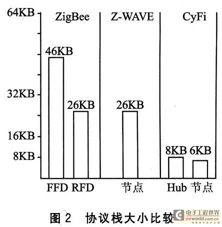
â‘¡ Simplify. The light-weight star protocol stack CYFISNP provided by CyFi has a very small size, which is only 8 KB for Hub and 6 KB for nodes, as shown in Figure 2. The CYFISNP protocol stack can be used directly in PSoCDesigner. The user module it provides allows developers to implement innovative wireless designs with simple drag and drop. Users do not need to write any communication protocol or code by themselves. The combination allows it to be reprogrammed at any stage of the development process.
â‘¢Low power consumption. In order to achieve low power consumption, CyFi tries to work in sleep mode. This means that in the case of weak interference, CyFi will transmit at the fastest speed (1 Mbps) to shorten the transmission time; in the case of strong interference, DSSS modulation technology will be enabled and the RF transmit power will be increased to 250 kbps transmission rate, thereby reducing the possibility of retransmission. When the distance between the node and the Hub is relatively short, the node can also reduce the transmission power and thus the power consumption. This effective power management mechanism allows typical sensor applications using CyFi to be used for only 4 years with only 2 AA batteries.
â‘£Multi-channel. Since CyFi only occupies a bandwidth of 1 MHz, there are as many as 80 channels available, while ZigBee can only use 16 channels of 5 MHz.
2 Introduction to CY3271
CY3271 is a low-cost USB interface kit with CyFi launched by Cypress for newcomers, including PSoC Integrated Development Environment PSoCDesigner, induction control software SCD for data acquisition, PC bridge with RF function FTPC, multi-function board FTMF, support FTRF, an RF expansion board with power amplifier for long-distance wireless applications, and 2 battery boards. Among them, the PC bridge FTPC is used as the Hub device of CyFi; the RF expansion board FTRF is used as the node device of CyFi and has an ultra-low power temperature sensor; and the multi-function board FTMF has CapSense touch sensors and proximity sensors , Temperature sensor, light sensor and red, yellow and blue LED lights. This article only uses the CapSense touch sensor as an example.
3 Hardware structure
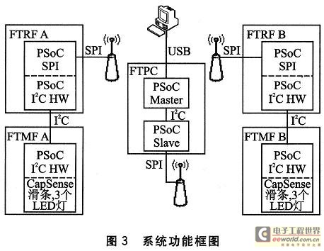
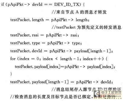
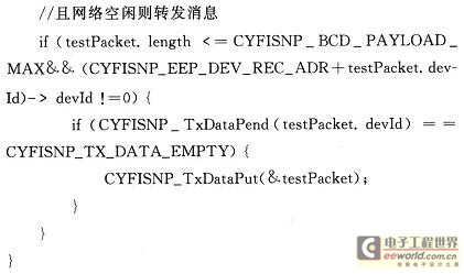
Because CyFi uses a star broadcast network protocol, all messages need to go through the central Hub, so the process of data communication from node A to node B is as follows: node A collects the position of the CapSense touch slider of multi-function board A through I2C protocol, The data such as the status of the 3 LED lights, and it is sent out through RF together with the ID number of the target node B; after the Hub detects that there is a message in the network, it forwards the message according to the target node ID in the message, and simultaneously transmits the data Save it in the cache and wait for the PC to read it; after receiving the message, Node B also controls the turning on and off of the three LED lights on the multi-function board B through the I2C protocol according to the data in the message. There are two PSoC cores in the FTPC of the device where the Hub is located: the master core implements the USB-I2C conversion and the programming functions of each board (including the slave core); the slave core implements the Hub function, and is connected to the master core through I2C. The functional block diagram of the system is shown in Figure 3.
4 Software design
4. 1 PSoC software design
The design examples of each PSoC are provided on the CD of the CY3271 kit. The design of the PSoC part in this article is modified on the basis of these examples. In order to realize the above function, the ID information of the destination node B needs to be added to the message sent by the node A, so that the Hub forwards the received message again. Each CyFi transceiver has two kinds of IDs; one is a 6-byte Radio ID, which is burned in when the transceiver is shipped from the factory, and cannot be changed and is unique in the world; the other is a 1-byte Node ID. It is determined when the node is bound, and can be specified in advance or can be dynamically allocated by the Hub. Because Ra-dio ID is more complex, developers can ignore RadioID during development and only focus on Node ID.
For the multi-function board A, you can directly use the MF_CS_SLIDE sample on the CD-ROM, without modification. For the RF_12C_BRIDGE sample used by node A, the main function needs to modify the parameters when calling the CyFiSNP_BindStart () function, as follows:
Among them, the type of message sent in the function sendNewTxMsg () that collects and sends messages must be modified to CYFISNP_API_TYPE_CONF_BCDR, and the following sentence should be added to the loadTxData () function called to add the ID information of Node B:
txApiPkt. payload [I2C_PAYLOAD_MAX] = DEV_ID_RX;
For the RF_HUB sample used by Hub, you first need to set the Device ID assignment attribute of the user module CYFISNP to Preas-signed Device ID, so that nodes A and B can bind successfully using the specified ID. After recompilation, after receiving the CYFISNP_API_TYPE_CONF_BCDR type message in the ServeSNPPackets () function, add the following code:
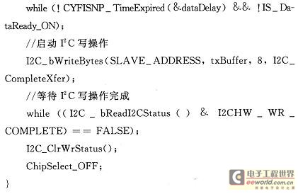
For the RF_I2C_BRIDGE sample used by Node B, its main function also needs to modify the parameters of the CYFISNP_BindStart () function, and it also needs to temporarily store the received message. The core code is as follows:
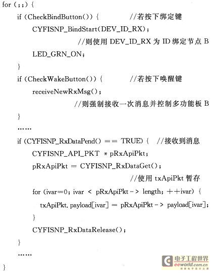
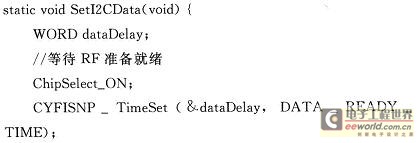
Among them, the function receiveNewRxMsg () responsible for receiving messages and controlling the multi-function board B must modify the message type to CYFISNP_API_TYPE_CONF_BCDR corresponding to node A, and the SeTI2CData () function called in it is as follows:
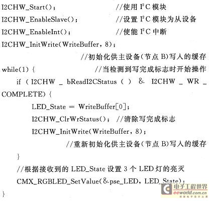
For the MF_CS_SLIDE sample used by multifunction board B, first use the project cloning function of PSoC Designer to clone the system-level project written in PSoCExpress in the sample into a chip-level project of PSoC Designer, otherwise the code in the program cannot be directly modified. Then add the following core code in the main function:
In this way, all five parts of the PSoC program are written, and finally each program is compiled separately and then burned into each board using the PSoC Programmer.
4.2 Software design of the host computer
Although the software CD for data acquisition and induction control has been included in the CD-ROM of CY3271, in order to clarify the reading and writing process of the USB interface of the FTPC device, and to port the Hub to other platforms in the future, a high-level function with customizable functions has been written. Machine software. This software is written in VisualC ++ 2005 and uses TeeChart chart display controls.
Because the FTPC device in CY3271 uses a USB interface to connect to the PC, and this USB device has been simulated as a standard HID device, the host computer software only needs to use the standard HID device control and read and write functions when communicating with the FTPC device. The reading and writing process of the FTPC device is roughly as follows:
â‘ Use the HidD_GetHidGuid () function to get the interface class GUID of the native HID device.
â‘¡ Use the SetupDiGetClassDevs () function to obtain the information collection of all devices in the HID class.
â‘¢ In the device information set, use the SetupDiEnumDevi-ceInterfaces () function to obtain the information of each device.
â‘£Use SetupDiGetDeviceInterfaceDetail () function to get detailed information of a certain device. To obtain detailed information about a device, this function must be called twice. The first call is to get the buffer size needed to save the device information, and the second call is to actually get the device detailed information.
⑤ After obtaining the detailed information of the device, use DevicePath in the device detailed information structure as the parameter of the Create File () function to open the specified device.
â‘¥ After opening the device, use the HidD_GetAttributes () function to obtain the attributes of the device (attributes include the manufacturer ID VID, product ID PID and product version number and other information). Then compare whether VID and PID are consistent with FTPC. If they are consistent (VID = 04B4, PID = F115), then exit the search, indicating that the device has been found; if not, switch to the next device, and then repeat the previous steps â‘¢ ~ â‘¥.
After finding the device, you can read and write data to the device. Use Bus Hound software to view USB devices and grab USB data packets. After analysis, it is found that the FTPC device uses the interrupt endpoint in the HID device to transfer data, so the ReadFile () and WriteFile () functions should be called to read and write. Since the FTPc device is a HID slave device, each read or write process of the FTPC device has the operation of writing first and then reading. In other words, when writing to the FTPC device, first write the relevant write command and the data to be written, and then read out the feedback of whether the writing was successful; when reading the FTPC device, first write the relevant read command, and then read the desire The data read.
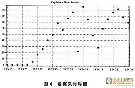
According to the above method, combined with the command defined in Hub's PSoC program and the result obtained by the Bus Hound packet capture, you can perform the corresponding operation on the Hub in the FTPC device, such as entering the binding state, reading the binding result, Read received messages, etc. After the node binding is successful, you can view the real-time data collection, including the time of data collection and the slider position value, as shown in Figure 4.
Conclusion
The emergence of CyFi has solved various problems in wireless sensor networks, and the user module method of PSoC has greatly facilitated developers. Developers can easily complete complex wireless sensors by simply dragging and dropping and adding simple code. Design and development of web applications. At the same time, the Hub device of the starter kit is simulated as a standard HID device, which also makes the development of application programs on the PC a breeze.
Active Professional Ktv Speaker,Top Speakers For Live Performance,Top Professional Performance Speakers,Portable Performance Speaker
NINGBO RFUN AUDIO TECHNOLOGY CO.,LTD , https://www.mosensound.com