With the continuous advancement of modern electrification, the demand for high-quality power distribution has significantly increased. Although various types of voltage regulators are gradually being upgraded, they still fail to effectively suppress harmonic distortions. In fact, the hazards caused by harmonics have become more severe and significant. Therefore, it is essential to conduct a qualitative analysis of how harmonics are generated and the damage they cause. This will help in better understanding the issue, leveraging the benefits while minimizing the harmful effects.
Harmonic hazards should be analyzed within the context of China’s power distribution system. China has long used a 50Hz AC power supply system. However, during the process of voltage regulation and protection, harmonic disturbances are often overlooked. This lack of attention creates favorable conditions for the generation and persistence of harmonics, leading to interactions that can damage equipment and waste a large amount of electrical energy. Table 1 shows the classification of positive, negative, and zero-sequence harmonics in a 50Hz AC power supply system.
Table 1: Harmonic Classification
Harmonic Number: 2 3 4 5 6 7 8 9 10
Frequency (Hz): 100 150 200 250 300 350 400 450 500
Phase Sequence: - 0 + - 0 + - 0 +
The presence of various harmonics distorts the standard 50Hz sinusoidal waveform, affecting normal operation. In three-phase four-wire power systems, integer multiples of third harmonics can accumulate on the primary side of the transformer, causing overheating of the coil and excessive neutral current, which may lead to burning out. During motor operation, harmonics severely distort the AC voltage waveform, potentially damaging the motor. In reactive power compensation circuits, harmonics can create resonance, leading to capacitor failure. Common household issues such as burnt-out fluorescent lamps or faulty starters are also attributed to harmonic distortion.
In addition to damaging the circuit, harmonics also limit the improvement of the power factor. When using capacitors to increase the power factor, the negative impact of harmonics becomes inevitable. If the harmonic content is high, the reactive compensation capacitors may be damaged or even explode.
Qualitative Analysis of Harmonics
Each harmonic plays a different role in the circuit. To better understand their effects, we will conduct a qualitative analysis of two common harmonic phenomena to identify their causes and find ways to suppress them.
2.1 Superposition Characteristics of Harmonics
The superposition of harmonics depends on their phase sequence. In the same circuit, some harmonics interact with each other, either reinforcing or canceling out. However, more often than not, they overlap, leading to significant waveform distortion. For example, when only the 3rd harmonic is present, the waveform appears as shown in Figure 1. When both the 3rd and 5th harmonics are present, the sine wave undergoes a noticeable change, as seen in Figure 2.
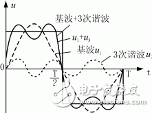
Figure 1: u1, u3, and their superimposed waveforms
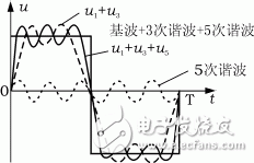
Figure 2: u1, u3, u5, and their superimposed waveforms
As more harmonics are added, the sine wave undergoes a qualitative transformation. A square wave, for instance, can be represented using a Fourier series as follows:
Ui = 4Um[sin(2πft) + (sin(6πft))/3 + (sin(10πft))/5 + ... + (sin(2kπft))/k]/π (1)
Where Ui is the voltage after superposition, Um is the amplitude of the fundamental wave, f is the frequency of the fundamental wave (50 Hz), and k = 1, 3, 5... represents odd numbers.
Other types of harmonic superposition exist as well, such as sawtooth waves, which contain a series of even harmonics (see Figure 3).
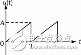
Figure 3: Sawtooth waveform
Its Fourier series expression is:
Ui = A/2 - A[sin(2πft) + (sin(4πft))/2 + (sin(6πft))/3 + ... + (sin(2kπft))/k]/π (2)
Where Ui is the voltage after superposition, A is the amplitude of the sawtooth wave, f is the fundamental frequency (50 Hz), and k is a natural number.
From this analysis, it is clear that harmonic superposition cannot be ignored. This is especially evident in three-phase four-wire power systems, where the neutral line may overheat due to excessive current, as shown in Figure 4. Additionally, overheating of the neutral busbar and terminal block in distribution lines is also caused by harmonic superposition.
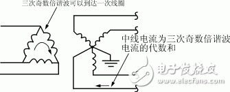
Figure 4: Neutral current in a three-phase four-wire power supply system
2.2 Characteristics of Higher Harmonics
Higher harmonics behave similarly to the fundamental wave, but instead of following low-impedance paths, they preferentially choose capacitive circuits. This is because capacitors block low frequencies and allow high frequencies to pass through. The reactance of a capacitor is given by Xc = 1/(2Ï€fC). As the harmonic frequency increases, the capacitive reactance decreases, allowing higher harmonic currents to flow more easily, thereby increasing the potential for damage. This effect is most pronounced in reactive power compensation circuits. Without proper analysis and measurement of harmonic content, relying solely on reactive power compensation to improve the power factor can lead to capacitor failure. Another common example of higher harmonic harm is the reduced lifespan of fluorescent lamps and the damage to starters in everyday use.
UL XLPE Cable,UL3385 electronic wire,High-temperature resistant wires,Irradiation cross-linked wires
Jiangyin City Weicheng Special Cable Co.,Ltd , https://www.weichengcable.com