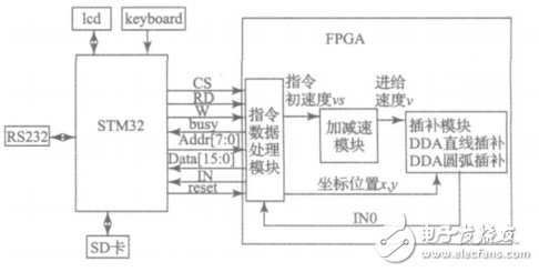
Figure 1: System principle
The STM32 reads data from an SD card and performs necessary algorithmic computations. The initial speed, maximum speed, acceleration values, and other control parameters are set through a keyboard scanning circuit. These parameters are then sent to the FPGA for further processing. The FPGA controls the pulse output and the timing between pulses, which is isolated using a high-speed optocoupler to drive the motor. Communication with the host computer is achieved via RS232, while an LCD interface enables user interaction. The FPGA is responsible for implementing key motion control functions such as command processing, acceleration/deceleration control, and interpolation algorithms (including linear and circular interpolation). **2. Implementation of Motion Control Algorithm in FPGA** **2.1. Implementation of Speed Control Algorithm in FPGA** To prevent issues like over-travel, impact, step loss, and oscillation during startup, operation, or speed changes, the system ensures smooth and accurate positioning by managing acceleration and deceleration transitions. Most motion control systems use either trapezoidal or S-curve acceleration profiles. Given the simplicity, fast response, and high efficiency of the trapezoidal method, this project enhances the traditional trapezoidal algorithm to generate pulse outputs. The trapezoidal acceleration/deceleration algorithm uses a pulse superposition technique, where a reference clock is divided into multiple frequencies without overlap. These pulses are combined according to equation (1) to produce continuously adjustable frequency outputs for smooth acceleration and deceleration.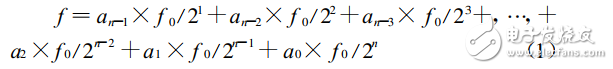
Equation (1): f0 / 2^n represents the frequency division of the reference pulse. The number of bits in the frequency divider counter determines the different pulse frequencies generated. The coefficient a[N:0] indicates the number of pulses per unit time, i.e., the pulse rate.
Based on this equation, the system logic structure under this method is shown in Figure 2.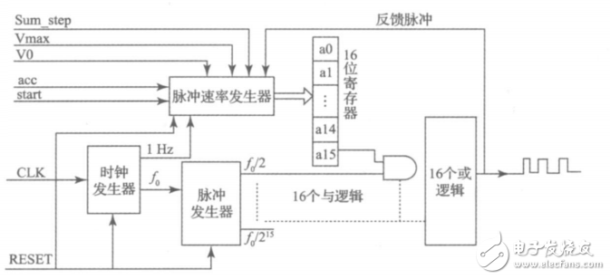
Figure 2: System logic structure circuit
The Hydrogel Film is made of a honeycomb structure with super toughness TPU material, which has a certain buffering effect to prevent falling, explosion-proof, and collision with sharp objects. It is an innovative product with slow rebound technology. Small scratches and bubbles can be automatically repaired after 24 hours.
Self-Repairing Films,Automatically Repair Hydrogel Screen Protector,Self Healing Hydrogel Film,Hd Self-Repair Screen Protector,Hd Anti-Stress Repair Hydrogel Screen Protector
Shenzhen TUOLI Electronic Technology Co., Ltd. , https://www.tlhydrogelprotector.com