The CPU and DSP's requirements for data processing speed continue to increase, and the power supply requirements for the power supply module have correspondingly increased. This is mainly reflected in the requirements of the power supply's output current, its rate of change, and the peak-to-peak output voltage. Compared with the disadvantages of pure hardware design such as the use of smart circuits, large capacity and low ESR capacitors that lack flexibility, the introduction of AVS not only benefits the thermal design of the power module, but also has a small peak-to-peak output voltage and short recovery time, effectively The dynamic response of the module is especially suitable for low voltage and high current situations.
The adaptive voltage adjustment AVS is based on tracking the performance changes of the system processor, and the adaptive voltage adjustment is made by the embedded adaptive advanced power controller (APC). APC accurately transfers the system processor's performance (frequency) and temperature changes to the external adaptive power management chip through the PowerWise interface. Then, the power management unit automatically adjusts the voltage supplied to the system processor according to performance requirements, so that the processor operates at the lowest voltage and frequency that can ensure that the application software operates correctly. The core of DVS and AVS is the Advanced Power Controller (APC). Figure 2 is a functional block diagram of AVS.
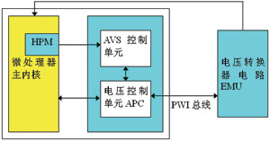
Figure 2 AVS block diagram of closed-loop control
In DVS mode, APC takes out the corresponding voltage value from the internal DVS table according to the frequency request from the clock management unit CMU and transmits it to the PMIC. Then use a timer to delay the CMU's confirmation of the frequency until the voltage is stable.
In the AVS working mode, when the CMU requests a new frequency for a new working state and sets a new HPM clock for the state, the AVS frequency begins to change. The APC loop controller then uses the hardware performance monitor HPM data to determine the required regulation frequency. It repeatedly adjusts the power supply voltage until it can meet the new frequency requirements (as shown in Figure 3). Although this process sounds complicated, it has the advantages of compensating for process and temperature fluctuations, clock frequency changes, and power converter offsets. Compared with a system with a fixed voltage, the dynamic voltage control achieved by the AVS mode can reduce power consumption by up to 70%.
At present, many processor chips support dynamic voltage and frequency control, such as InteI's chip supports SpeedStep, AMD's chip supports NCQ technology, ARM supports IEM (Intelligent Energy Manager) and AVS (AdapTIve Voltage Scaling). However, for dynamic voltage and frequency regulation to work and achieve real energy savings, only chip support is not enough, and a comprehensive design of software and hardware is required.
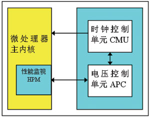
Figure 3 Schematic diagram of the control loop of AVS
The working process of a typical dynamic voltage and frequency adjustment system is as follows (see Figure 3 for main components and relationships).
â‘ Collect information related to the system load and calculate the current system load. This process can be implemented in software or hardware. The process of software implementation is to place a hook in the core call of the operating system, and use different algorithms to judge the load of the system according to the frequency of core function calls. CPU load tracking and performance prediction can also be done by hardware, such as Freecscale's i.Mx31, by collecting some core signal interrupt lines, Cache, memory bus usage, etc. to calculate the current system load. In this way, on the one hand, the accuracy of the load calculation is ensured; on the other hand, the burden of the CPU for load tracking and performance prediction is reduced. However, the disadvantage of hardware implementation is that it is not flexible to choose the prediction algorithm.
â‘¡ According to the current load of the system, predict the performance required by the system in the next time period. There are many prediction algorithms to choose from, depending on the specific application. Similarly, prediction can also be achieved by software or hardware.
â‘¢ Convert the predicted performance to the required frequency, thereby adjusting the clock setting of the chip.
④Calculate the corresponding voltage according to the new frequency, and notify the power management module to adjust the voltage supplied to the CPU. This requires special power management chips, such as Freescale's MC13783 or NS's series of power management chips that support PowerWise features. They can support tiny voltage adjustment (25mV) and can complete the voltage adjustment in a very short time (tens of μs).
In summary, the standard system configuration that supports closed-loop AVS functions must have the following basic components: an advanced power controller APC built into the processor, a power management chip with integrated PWI slave, and a PWI string that connects the two together行 BUS。 Line bus. The power management integrated circuit is responsible for providing different voltages for the processor, and the voltage is regulated by the PWI master in the advanced power controller. The method is that the master transmits the relevant commands to the PWI slave, and then the related The circuit is adjusted.
The advanced power controller APC is responsible for receiving commands from the main processor, providing an operating environment unaffected by the processor for the voltage control process, and tracking the operating speed of the logic circuit in real time. APC is always on alert, constantly monitoring all system parameters, such as system temperature, load, transient, process and other related changes. When APC receives a message about the frequency is about to change, it immediately analyzes and judges to determine if With new frequency operation, the system needs at least how much power supply voltage to maintain stability. The entire process is monitored by a closed-loop circuit.
Other issues to consider
The voltage drop will cause the threshold level of the pins that interface with the external chip to change. When connected to external logic, you must use level conversion logic to switch to adapt to the threshold level on both sides of the interface. For example, an AVS circuit with a voltage of 0.8 to 1.2V and a circuit interface with a fixed voltage of 1.2V, then the interface logic of the AVS circuit must be designed according to the 1.2V interface. Similarly, due to the frequency change that may be caused by DVS or AVS, when designing an interface with an external synchronization circuit, the timing margin of the interface must be calculated. If the timing cannot be completely matched, additional synchronization or delay circuits need to be added for timing Adjustment.
When adjusting the frequency and voltage, pay special attention to the order of adjustment. When the frequency is adjusted from high to low, the frequency should be lowered before the voltage is lowered; on the contrary, when the frequency is increased, the voltage should be raised first and then the frequency.
The output voltage range and the slope during the voltage change are two parameters that must be considered. During the DVS period when the voltage changes, the slope of the output voltage must be controlled. External components can be used for control, or a speed-adjusting capacitor that can reduce the reference voltage change internally, or a smaller step size (such as 25mV) ) A digital counter that adjusts the output voltage from the initial value to the target value.
The decreasing voltage level also puts forward higher requirements on the accuracy of the output voltage. Therefore, it is generally difficult to find a suitable standard device to meet related needs. If an external feedback voltage divider is used, the tolerance of the resistor will increase the total tolerance of the internal circuit. The overall accuracy in this type of system is always lower than the solution with an internal fixed output voltage, although the latter requires 2 additional external components. Therefore, for a converter that uses an internal resistance voltage divider that can be fine-tuned during operation, it is necessary to define a series of different voltages and achieve an overall DC accuracy of ± 1% in the temperature range of -40 to + 85 ° C.
In order to achieve the best transient response or lower output voltage tolerance under different load conditions, other measures must be taken. In addition to the internal design, external components must also be optimized. With a lower inductance value, the current can be increased at a faster rate, which is especially suitable for fast transient response. Under transient conditions, if there is no load, a lower inductance value is more advantageous because it will only charge the output capacitor at a lower voltage and have a lower voltage overshoot.
The other most critical factor that affects the widespread use of dynamic voltage and frequency regulation techniques is the reliability of predictions. No prediction algorithm is 100% accurate, and no algorithm can be applied to all programs; and for some applications (such as audio, video, etc.), the result of prediction failure is unacceptable. But with the advancement of prediction algorithms, dynamic voltage and frequency control technology will be widely used, because it can save a lot of energy. For many portable devices, energy saving is often the first requirement.
A class lithium cells
Superior selection for materials & parts
Exquisite workmanshipHandicraft grade look and workmanship
High class ABS container with abrasive coating
High class brass terminals makes low internal resistance and strong discharge performance
Iron phosphate lithium ion battery cathode material for lithium iron phosphate, its safety performance and cycle life is obviously can not be compared to other materials. Iron lithium battery to solve the security problem of general battery, the general battery will produce explosion in a strong collision, hidden safety problems; While the lithium iron phosphate batteries has been rigorous safety testing, even if the internal or external battery damage, also will not burn, not explode. The cycle life of the battery is normal in general about 300 times, the highest is about more than 500 times, the use of time is generally 1 to 1.5 years; While the lithium iron phosphate batteries, the cycle life of more than 2000, the standard charge (2 hours), can reach 2000 times, using the time can reach more than 4 years, it is 2 times more than the normal battery; These power battery technology index is one of the most important.
Lithium Sli Battery,Lithium Starting Batteries,Lihthium Car Battery,Lithium Car Starting Battery
Starlight Power Industrial Company Limited , https://www.starlite-power.com