For optimizing the efficiency and reliability of solar systems, a newer approach is to use micro-inverters connected to each solar panel. Equipping each solar panel with a separate micro-inverter allows the system to adapt to changing loads and weather conditions, thereby providing the best conversion efficiency for a single panel and the entire system.
The micro-inverter architecture also simplifies wiring, which means lower installation costs.
By making consumers' solar power generation systems more efficient, the time required for the system to "recover" the initial investment in solar technology will be reduced.
Power inverter is a key electronic component of solar power generation system. In commercial applications, these components connect photovoltaic (PV) panels, batteries that store electrical energy, and local power distribution systems or utility grids. Figure 1 shows a typical solar inverter, which converts the extremely low DC voltage output from the photovoltaic array into several voltages such as battery DC voltage, AC line voltage, and distribution network voltage.
In a typical solar energy collection system, multiple solar panels are connected in parallel to an inverter that converts the variable DC output from multiple photovoltaic cells into a clean 50Hz or 60Hz sine wave inverter power supply.
In addition, it should also be noted that the microcontroller (MCU) module TMS320C2000 or MSP430 in Figure 1 usually contains key on-chip peripherals such as pulse width modulation (PWM) modules and A / D converters.
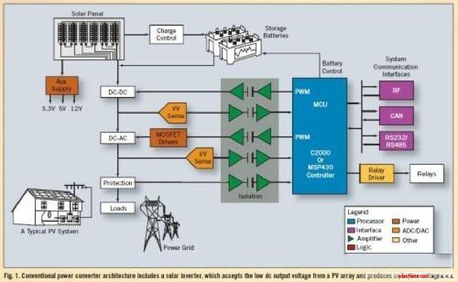
Figure 1: The traditional power conversion architecture contains a solar inverter that receives a low DC output voltage from the PV array and generates AC line voltage.
The main goal of the design is to increase the conversion efficiency as much as possible. This is a complex and iterative process, which involves the maximum power point tracking algorithm (MPPT) and a real-time controller that executes the relevant algorithms.
1 Maximize power conversion efficiency
Inverters that do not use the MPPT algorithm simply connect the photovoltaic module directly to the battery, forcing the photovoltaic module to work at the battery voltage. Almost without exception, the battery voltage is not an ideal value for collecting the most available solar energy.
Figure 2 illustrates the traditional current / voltage characteristics of a typical 75W photovoltaic module at a cell temperature of 25 ° C. The dotted line indicates the ratio of voltage (PV VOLTS) to power (PV WATTS).
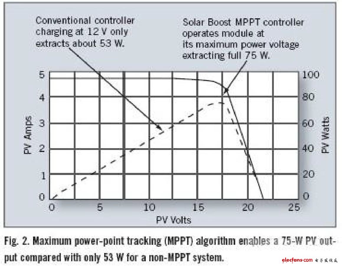
The solid line shows the ratio of voltage to current (PV AMPS). As shown in Figure 2, at 12V, the output power is approximately 53W. In other words, by forcing the photovoltaic module to work at 12V, the output power is limited to about 53W.
But after using the MPPT algorithm, the situation has fundamentally changed. In this example, the voltage at which the module can achieve maximum output power is 17V. Therefore, the responsibility of the MPPT algorithm is to make the module work at 17V, so that no matter what the battery voltage is, you can get all 75W of power from the module.
The high-efficiency DC / DC power converter converts the 17V voltage at the input of the controller into the battery voltage at the output. Since the DC / DC converter reduces the voltage from 17V to 12V, in this example, the battery charging current in the system that supports the MPPT function is:
(VMODULE / VBATTERY) & TImes; IMODULE, or (17V / 12V) & TImes; 4.45A = 6.30A.
Assuming that the conversion efficiency of the DC / DC converter is 100%, the charging current will increase by 1.85A (or 42%).
Although this example assumes that the inverter is processing energy from a single solar panel, the traditional system is usually an inverter connected to multiple panels. Depending on the application, this topology has both advantages and disadvantages.
2 MPPT algorithm
There are three main types of MPPT algorithms: disturbance-observation method, conductance increment method and constant voltage method. The first two methods are commonly referred to as "hill climbing" methods because they are based on the following facts:
On the left side of MPP, the curve shows an upward trend (dP / dV >> 0), while on the right side of MPP, the curve decreases (dP / dV <0).
The disturbance-observation (P & O) method is the most commonly used. The algorithm disturbs the operating voltage in a given direction and samples dP / dV. If dP / dV is positive, the algorithm “understands†that it was just adjusting the voltage towards MPP. Then it will adjust the voltage in this direction until dP / dV becomes negative.
P & O algorithms are easy to implement, but in steady-state operation, they sometimes oscillate near MPP. And their response speed is slow, even under rapidly changing climate conditions, it is possible to reverse the direction.
The incremental conductance (INC) method uses the conductance increment dI / dV of the photovoltaic array to calculate the positive and negative of dP / dV. INC can track rapidly changing light irradiation conditions more accurately than P & O. But like P & O, it may also oscillate and be "deceived" by rapidly changing atmospheric conditions. Another disadvantage is that the increased complexity will increase the calculation time and reduce the sampling frequency.
The third method "constant pressure method" is based on the following facts: In general, VMPP / VOC: 0.76. The problem with this method is that it needs to instantly adjust the current of the photovoltaic array to 0 to measure the open circuit voltage of the array. Then, the working voltage of the array is set to 76% of the measured value. But during the period when the array is disconnected, the available energy is wasted. It has also been found that although 76% of the open circuit voltage is a good approximation, it is not always consistent with MPP.
Since no MPPT algorithm can successfully meet all common usage environment requirements, many design engineers will let the system first estimate the environmental conditions and then select the algorithm that best suits the environmental conditions at the time. In fact, there are many MPPT algorithms available, and it is not uncommon for solar panel manufacturers to provide their own algorithms.
For cheap controllers, in addition to the normal control functions of the MCU, it is not easy to execute the MPPT algorithm. The algorithm requires these controllers to have superb computing power.
Advanced 32-bit real-time microcontrollers such as the Texas Instruments C2000 platform series are suitable for various solar applications.
3 Power inverter
There are many benefits of using a single inverter, the most prominent of which is simplicity and low cost. Using MPPT algorithm and other technologies improves the efficiency of single inverter system, but this is only to a certain extent. Depending on the application, the disadvantages of a single inverter topology will be obvious. The most prominent is the reliability problem: as long as the inverter fails, the energy generated by all the panels is wasted before the inverter is repaired or replaced.
Even if the inverter works normally, a single inverter topology may have a negative impact on system efficiency. In most cases, to achieve the highest efficiency, each solar panel has different control requirements. The factors that determine the efficiency of each panel are: the manufacturing differences of the photovoltaic cell components contained in the panel, the different light intensities (the original solar energy received) caused by different environmental temperatures, shadows and orientation.
Compared with using an inverter for the entire system, equipping each solar panel in the system with a micro-inverter will again improve the conversion efficiency of the entire system. The main benefit of the micro-inverter topology is that even if one of the inverters fails, the energy conversion can still be performed.
Other benefits of using micro-inverters include the ability to use high-resolution PWM to adjust the conversion parameters of each solar panel. Since clouds, shadows and shades change the output of each panel, equipping each panel with a unique micro-inverter allows the system to adapt to changing load conditions. This provides the best conversion efficiency for each panel and the entire system.
The micro-inverter architecture requires each panel to have a dedicated MCU to manage energy conversion. However, these additional MCUs can also be used to improve system and panel monitoring.
For example, large solar farms benefit from communication between panels to help maintain load balance and allow system administrators to plan in advance how much energy is available and what to do with that energy. However, to take full advantage of the benefits of system monitoring, the MCU must integrate on-chip communication peripherals (CAN, SPI, UART, etc.) in order to simplify the interface with other micro-inverters in the solar array.
In many applications, the use of micro-inverter topology can significantly improve the overall system efficiency. At the panel level, efficiency is expected to increase by 30%. However, the "average" percentage of system-level improvement does not make much sense due to the wide variation among applications.
Application analysis When * estimating the value of a micro inverter in a specific application, the topology should be considered from several aspects.
In small applications, each panel may face substantially the same conditions of light, temperature, and shadow. Therefore, micro-inverters have a limited role in improving efficiency.
In order to make each panel work at different voltages to obtain the highest energy efficiency, it is required to adopt a DC / DC converter to make the output voltage of each panel unified with the working voltage of the energy storage battery. In order to reduce the manufacturing cost as much as possible, the DC / DC converter and inverter can be designed as a module. DC / AC converters used for local power lines or connected to the distribution network can also be integrated into the module.
Solar panels must communicate with each other, which increases wiring and complexity. This is another point of contention for the inclusion of inverters, DC / DC converters and solar panels in the module.
The MCU of each inverter must still have sufficient capacity to run multiple MPPT algorithms to adapt to different operating environments.
The use of multiple MCUs will increase the material cost of the overall system.
Whenever you consider changing the architecture, you pay attention to its cost. To meet the price target of the system, equipping each panel with a controller means that the cost of the controller must be competitive and the form factor is small, but it can still handle all control, communication, and computing tasks simultaneously.
On-chip integration of appropriate control peripherals and a high degree of analog integration are the two basic elements that ensure the low cost of the system. High performance is also necessary to execute algorithms developed for efficiency in the various links of optimized conversion, system monitoring and energy storage.
In addition to meeting the requirements of the micro-inverter itself, MCUs that can handle most of the requirements of the entire system, including AC / DC conversion, DC / DC conversion, and inter-panel communication, can reduce the cost caused by using multiple MCUs increase.
4 MCU features
Carefully weighing these high-level requirements is the best way to determine which functions the MCU needs. For example, load balancing control is required when panels are connected in parallel. The selected MCU must be able to detect the load current and raise or lower the output voltage by turning on / off the output MOSFET. This requires a high-speed on-chip ADC to sample voltage and current.
There is no "unchanged" model for the design of micro-inverters. This means that designers must have the ability and innovative spirit to adopt new techniques and technologies, especially in the communication between panels and systems. The most suitable MCU should support various protocols, including some things that are not normally thought of, such as power line communication (PLC) and controller area network (CAN). Especially for power line communication, since no special communication line is needed, the system cost can be reduced. But this requires MCU built-in high-performance PWM, high-speed ADC and high-performance CPU.
For MCUs designed for solar inverter applications, an unexpected but extremely valuable feature is the dual on-chip oscillators, which can be used for clock failure detection to improve reliability. The ability to run two system clocks at the same time also helps reduce the problems that arise when installing solar panels.
With so many innovations condensed in the design of solar micro-inverters, for MCUs, perhaps the most important feature is software programming capabilities. This feature enables the highest flexibility in power circuit design and control.
The C2000 microcontroller is equipped with an advanced digital arithmetic processing core that can efficiently process arithmetic operations and an on-chip peripheral set for energy conversion control. It has been widely used in traditional solar panel inverter topologies. The newly launched Piccolo series C2000 series microcontrollers are economical models. The smallest package of this series is only 38 pins, but the architecture is more advanced and the peripherals are also enhanced, so that the benefits of 32-bit real-time control can be brought to low requirements. Applications such as micro inverters for overall system cost.
In addition, each product in the Piccolo MCU series integrates two on-chip 10MHz oscillators for clock comparison, as well as on-chip VREG with power-on reset and power-down protection, multiple high-resolution 150ps PWM, and a 12-bit 4.6 Megasamples / second ADC and communication protocol interfaces such as I2C (PMBus), CAN, SPI and UART. Figure 3 shows a computer system configuration used with a micro-inverter-based photovoltaic system.
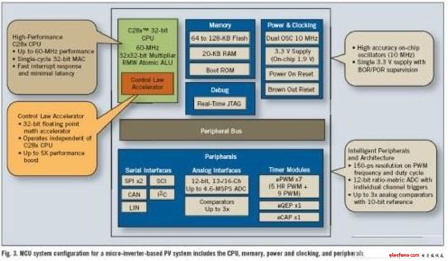
Figure 3: MCU system for a system based on a micro-inverter PV includes a CPU, memory, power supply, clock, and peripherals.
Performance is a key characteristic of micro inverters. Although Piccolo series devices are smaller and cheaper than other C2000 MCU products, their functions have been improved. For example, it has a programmable floating-point control law accelerator (CLA) that can share complex high-speed control algorithms for the CPU. The CPU does not need to deal with I / O and feedback loops. In closed-loop applications, it can improve performance by 5 times.
5 Challenges of photovoltaic cells
One of the disadvantages of solar power generation systems is the conversion efficiency. Solar panels can obtain an average power of about 1mW from every 100mm2 of photovoltaic cells. Typical efficiency is about 10%. The power factor of the photovoltaic power supply (that is, the ratio of the average energy actually produced by the solar cell to the theoretically produced electricity under the conditions of continuous sunlight) is about 15% to 20%.
There are various reasons for this result, including changes in the sunlight itself, such as the complete disappearance at night, and even during the daytime, shadows and weather conditions often lead to reduced light.
Photoelectric conversion introduces more variables for efficiency calculations, including the temperature of the solar panel and its theoretical peak efficiency. For the design engineer, another problem is that the voltage generated by the photovoltaic cell has an irregular change of about 0.5V. When choosing the energy conversion topology, this change will have a serious impact. For example, for inefficient energy conversion technology, it may consume a large part of the photovoltaic energy collected.
In order to adapt to the fact that the sun does not shine 24 hours a day, solar-powered systems include batteries and the complex electronics required to efficiently charge the batteries. When the battery is integrated into the system, battery charging requires an additional DC / DC conversion circuit, as well as battery management and monitoring.
Many solar-powered systems also interface with the grid, requiring phase synchronization and power factor correction. There are many use environments that require complex control. For example, a failure warning mechanism must be built in to prevent events such as power outages in the public grid. These are just the top priorities that design engineers must consider.
MC Wall series Wall Hanging LED Display
P1.66, P1.875, P1.923, P2, P2.5, P3.07, P3.91
Wall Hanging Led Display classical and stable structure and performance.
1. Two protected strong locks design, realizing
combination of reliability and security.
2. Die-casting aluminum body, lightweight for easy
transportation and high accuracy installation.
3. Perfectly be compatible with any existing controller
and without screen shaking/quick flashing/mosaic problems.
4. Supporting installation of hanging/ground mounting,
for stage/TV show/studio, and other event applications.
Wall Hanging Led Display is highly usable at indoor places like Airport, subway station,malls, stages, chain stores, hotels, public buildings, bars, restaurants, etc. Its thin size and ultra-lightweight module makes it easy to install at any area without covering much space.
Wall Hanging Led Display
Wall Hanging Led Display,LED Wall Display,Movable Wall Hanging LED Display,Wall Hanging Small LED Display
Shenzhen Macion Optoelectronics Technology Co.,Ltd. , https://www.macion-led.com